


22
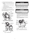
Insulate Motor Terminals and Lead Wire Ends — Locate
heat shrink tubing (RCD P/N LF33MM114) over power
connections so that they are completely covered and
tubing is against motor housing. Shrink into position.
Slide foam tubing (3 in. inner diameter closed cell vinyl,
neoprene, or nitrile foam) part way over the heat shrink
tubing. Apply adhesive for closed cell foam insulation to
motor side end of the foam tubing and push tubing the
rest of the way over the terminal and against the sheet
insulation on the motor side. Secure the opposite end of
the foam tubing with a wire tie as shown in Fig. 28.
Alternate Insulation for Motor Terminals and Lead Wire
Ends — Insulate compressor motor terminals, lead wire
ends, and electrical wires to prevent moisture condensa-
tion and electrical arcing. Obtain Carrier approved insula-
tion material from RCD (Replacement Components
Division) consisting of 3 rolls of insulation putty and one
roll of vinyl tape.
a. Insulate each terminal by wrapping with one layer
of insulation putty (RCD P/N 19EA411-1102).
b. Overwrap putty with 4 layers of vinyl tape.
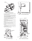
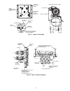
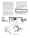
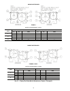
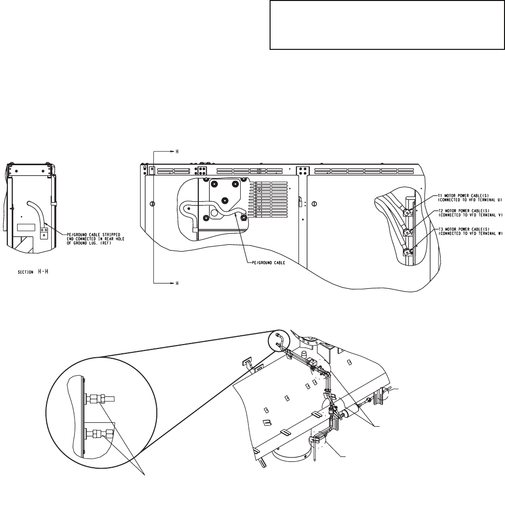
6. Orient PE/ground lug as shown in Fig. 28. Assemble
internal/external tooth lock washer between the terminal
box frame and the PE/ground cable. Torque PE/ground
lug nut to 55 to 65 ft-lb (75 to 89 N-m). See section H-H
in Fig. 29 for PE/ground cable routing.
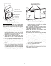
7. Center terminal enclosure frame over terminal box frame
assembly so the space between the frames is equal within
3
/
16
-in. (5 mm) at the top and bottom. Use the slots in the
terminal enclosure frame. Adjust spacing between the
sides of the terminal enclosure frame and terminal box
frame assemblies by moving the control center to the left
or right.
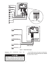
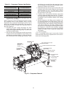
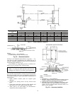
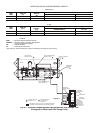
8. Install O-rings on VFD refrigerant connections using
silicone grease. Tighten connector using two wrenches to
27 to 33 ft-lb (37 to 45 N-m). (See Detail A in Fig. 30.)
9. Evacuate all piping between the VFD and the VFD isola-
tion valves after assembly and tightening of VFD fittings.
Dehydration/evacuation is complete to equalize VFD
piping pressure with machine pressure if machine is
charged with refrigerant (see Fig. 30).
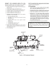
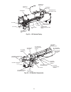
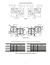
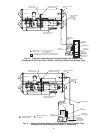
Install Machine Supports
INSTALL STANDARD ISOLATION — Figures 31 and 32
show the position of support plates and shear flex pads, which
together form the standard machine support system.
Service clearance under the chiller can be enhanced if the
grout is not extended along the entire length of the heat
exchangers.
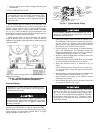
IMPORTANT: Chiller housekeeping pad, anchor
bolts and attachment points to be designed by others in
accordance with all applicable national and local
codes.
VFD COOLING
LINE O-RING
FACE SEAL
COUPLINGS
DETAIL A
SEE
DETAIL A
FILTER DRIER
ISOLATION VALVE
VFD ISOLATION
VALVES (2)
FILTER DRIER
ISOLATION VALVE
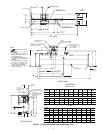
Fig. 29 — Motor Ground Cable
Fig. 30 — VFD Refrigerant Connectors
a23-1578
a23-1579