


18
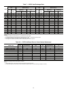
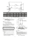
Table 10 — Compressor Fastener Identification
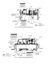
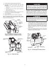
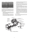
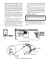
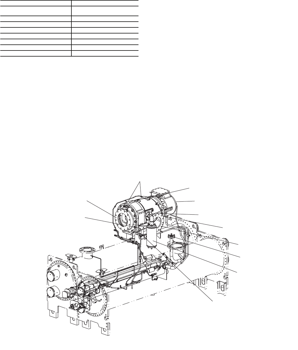
1. Disconnect the oil supply line in two places (Fig. 23).
Cap the oil lines and fittings.
NOTE: Compressor oil lines and fittings between the oil filter
and compressor must be kept extremely clean to prevent
obstruction of the compressor inlet bearing oil orifice. Cap all
orifice lines and fittings during disassembly. The compressor
inlet bearing oil orifice is located at the lubrication block on
top of the compressor.
2. Disconnect the motor cooling inlet flange, the motor
cooling drain flange, optional economizer vapor line
flange, and bearing oil drain flange (Fig. 23). Remove the
economizer muffler bracket.
3. Brace the end of the discharge pipe assembly closest to the
compressor if it has not already been removed. Place an oil
pan under the compressor flange to collect oil that may
have accumulated in the discharge pipe assembly. Unbolt
the discharge pipe assembly from the compressor. It may
also be necessary to loosen the bolts that attach the dis-
charge pipe assembly to the condenser.
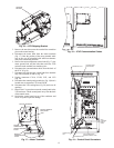
4. If the cooler has been removed, rig the suction elbow and
unbolt the suction elbow at the compressor and vaporizer
vent line flanges (see Fig. 12). If the cooler is still in
place, it may be necessary to loosen the bolts that secure
the suction elbow to the cooler.
5. Carefully remove the perforated insulation cutouts that
cover the compressor lifting points. See Fig. 23. Replace
the lifting shackle thread protector after the compressor is
re-installed to prevent insulation adhesive from fouling
the threads.
6. Rig the compressor with lifting eyelets installed in the
two M30 threaded holes provided in the top of the com-
pressor housing (Fig. 23). Use only M30 forged eye bolts
or M30 hoist rings with a sufficient working load limit to
safely lift the compressor. The rubber vibration isolators
may pull out of the compressor mounting bracket when
the compressor is lifted off of the condenser. Applying
leak detection soap solution to the outside of the vibration
isolators will make it easier to press the isolators back
into position.
7. Cover all openings.
NOTE: To reassemble, follow steps in reverse order. Connect
sensors and cables after major components have been secure to
reduce the risk damaging them.
COMPRESSOR FASTENERS SIZE
Discharge Pipe Assembly to
Compressor Discharge Flange
1 in.-8 Grade 5 Hex Head
Suction Elbow to Compressor Inlet
7
/
8
in.-9 Grade 5 Hex Head
Compressor Mount to Condenser
3
/
4
in.-10 Studs (A-449)
Economizer Line
5
/
8
in.-11 Grade 8 Hex Head
Motor Cooling, Motor Drain, Oil Drain M 12x1.75 Grade 10.9 Socket Head
Compressor Lifting Points (2) M30x3.5 Threaded Holes
Stator Housing Lifting Point M30x3.5 Threaded Hole
Discharge Housing Lifting Point M30x3.5 Threaded Hole
ECONOMIZER
MUFFLER
BRACKET
DISCHARGE
PIPE ASSEMBLY
BOLTING
FLANGE
OIL SUPPLY LINE
FITTINGS
M30 COMPRESSOR LIFTING
SHACKLE HOLES
MOTOR COOLING INLET FLANGE
ECONOMIZER VAPOR
LINE FLANGE
MOTOR COOLING
DRAIN FLANGE
SUCTION ELBOW
FLANGE
VAPORIZER VENT
LINE FLANGE
ECONOMIZER
MUFFLER
(OPTIONAL)
BEARING OIL
DRAIN FLANGE
Fig. 23 — Compressor Removal
a23-1572