


31
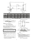
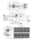
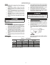
Table 11 — Relief Valve Locations
NOTE: All valves relieve at 185 psi (1275 kPa).
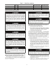
These instructions are intended for qualified electrical per-
sonnel familiar with servicing and installing AC drives. Any
questions or problems with the products described in this man-
ual should be directed to your local Carrier Service Office.
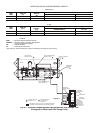
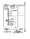
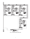
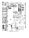
Wiring diagrams in this publication are for reference only
and are not intended for use during actual installation; follow
job specific wiring diagrams.
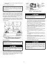
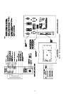
GROUNDING THE CONTROLS/DRIVE ENCLOSURE —
Use the following steps to ground the drive.
1. Open the left door of the control center.
2. Run a suitable equipment grounding conductor unbroken
from the drive to earth ground. Tighten these grounding
connections to the proper torque. See Fig. 6 and 29.
3. Close the door to the control center.
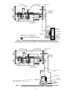
INSTALLING INPUT POWER WIRING — All wiring should
be installed in conformance with the applicable local, national,
and international codes (e.g., NEC/CEC). Signal wiring, control
wiring, and power wiring must be routed in separate conduits to
prevent interference with the drive operation. Use grommets,
when hubs are not provided, to guard against wire chafing.
Use the following steps to connect AC input power to the
main input circuit breaker:
1. Turn off, lock out, and tag the input power to the drive.
2. Remove the input power wiring panel above the VFD
circuit breaker and drill the number of openings for the
AC input leads (refer to Fig. 6). Mount all conduit hard-
ware on the input power wiring panel before re-installing
the input power wiring panel on the VFD enclosure.
Take care that metal chips and hardware do not enter the
enclosure.
3. Wire the AC input leads by routing them through the
openings in the input power wiring panel.
4. Connect the three-phase AC input power leads (per job
specifications) to the appropriate input terminals of the
circuit breaker. See Fig. 6.
5. Tighten the AC input power terminals and lugs to the
proper torque as specified on the input circuit breaker.
LOCATION
FRAME
SIZE
RELIEF VALVE OUTLET SIZE
QUANTITY WITHOUT
ISOLATION VALVES
QUANTITY WITH
ISOLATION VALVES
Discharge Pipe Assembly 3-5 1
1
/
4
-in. NPT FEMALE CONNECTOR 0 1
Cooler 3-5 1
1
/
4
-in. NPT FEMALE CONNECTOR 2 1
Condenser 3-5 1
1
/
4
-in. NPT FEMALE CONNECTOR 2 2
Optional Storage Tank N/A 1-in. NPT FEMALE CONNECTOR 2 2
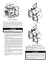
DC bus capacitors in the VFD retain hazardous voltages
after input power has been disconnected. After disconnect-
ing input power, wait 5 minutes for the DC bus capacitors
to discharge then check both the VFD DPI Communica-
tions Interface Board Status LEDs and the VFD with a
voltmeter to ensure the DC bus capacitors are discharged
before touching any internal components. Failure to
observe this precaution could result in severe bodily injury
or loss of life.
The drive can operate at and maintain zero speed. The user
is responsible for assuring safe conditions for operating
personnel by providing suitable guards, audible or visual
alarms, or other devices to indicate that the drive is operat-
ing or may operate at or near zero speed. Failure to observe
this precaution could result in severe bodily injury or loss
of life.
Do not install modification kits with power applied to the
drive. Disconnect and lockout incoming power before
attempting such installation or removal. Failure to observe
this precaution could result in severe bodily injury or loss
of life.
The drive contains ESD (Electrostatic Discharge) sensitive
parts and assemblies. Static control precautions are
required when installing, testing, servicing, or repairing the
drive. Erratic machine operation and damage to, or destruc-
tion of, equipment can result if this procedure is not
followed. Failure to observe this precaution could result in
bodily injury.
The user is responsible for conforming with all applicable
local, national and international codes. Failure to observe
this precaution could result in damage to, or destruction of,
the equipment.
Do not attempt to start compressor (even for a rotation
check) or apply test voltage of any kind while machine is
under dehydration vacuum. Motor insulation breakdown
and serious damage may result.
Low oil level may result if the oil pump is manually oper-
ated for more than a few minutes when the chiller is not
running. The oil reclaim system does not return oil to the
sump when the compressor is de-energized.
Do not route signal and control wiring with power wiring
in the same conduit. This can cause interference with con-
trol and drive operation. Failure to observe this precaution
could result in damage to, or destruction of, the equipment.