


22
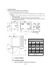
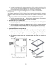
(3) The steamer is typically installed with four adjustable mounting legs, as shown in the dimension
drawing. The steamer must be level both front to back and side to side. Select an operating
surface that is level enough to allow leveling the unit without extreme adjustment of the legs
or shimming of surface mounts.
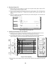
(4) The counter area selected must be capable of
supporting an operating weight of approximately 260
pounds to include the weight of water and food.
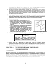
(5) Do not block the vents on the side or rear of the unit. Do
not store articles on top of the unit.
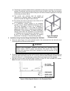
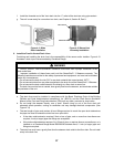
(6) If a satisfactory counter location is not available,
consider using a Model ES222834 Equipment Stand.
This stand, illustrated in Figure 4-2, is designed to
support the SteamChef¥ 3, and meets all necessary
support and safety criteria. A stacking stand, Model No.
ES222824S, is also available. The Model ES222834S
stacking stand allows the installation of two SteamChef
¥ 3 Steamers one on top of the other. See Section 1, Part
B and C for the installation instructions for installing
SteamChef¥ 3 steamers on Cleveland Range Stands.
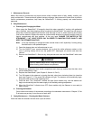
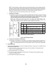
2. Installation Using Cleveland Range Stand Model No. ES222834.
a. Move the stand (Figure 4-2) to the selected location. We recommend that the feet with round
mounting pads be at the rear of the steamer.
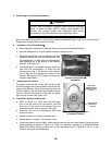
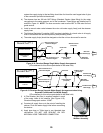
b. Set the unit on the stand with the front of the unit flush with the front edge of the stand. Mount the
unit to the stand from below using the 1/2 x 0.750 lg. bolts and fender washers provided with the
Stand Kit (Figure 4-3, on following page) installed into the rear leg mounts of the steamer.
c. Seal the unit to the stand around the edge as shown in Figure 4-3, with a suitable RTV sealant.
Note: Be careful not to seal the side panels to the steamer.
Figure 4-2 ES222834
E
q
ui
p
ment Stand
WARNING
INJURY AND EQUIPMENT DAMAGE could result from improper lifting. A
Model Number 22CET3 weighs approximately 250 pounds. Use enough
workers with experience lifting heavy equipment to place the steamer on the
supporting surface.
Figure 4-3 Mounting the Steamer on the Equipment Stand