


CY4672 Reference Design Guide, Document # 001-16968 Revision ** 35
Mouse
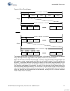
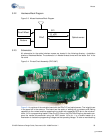
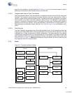
3.2.2 Hardware Block Diagram
Figure 3-3. Mouse Hardware Block Diagram
3.2.3 Schematics
All schematics for the optical wireless mouse are located in the following directory: <installation
directory>\Hardware\Mouse. The schematic is in Adobe Acrobat format with the letters ‘Sch’ in the
file name.
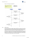
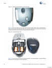
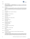
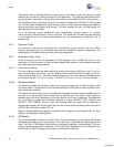
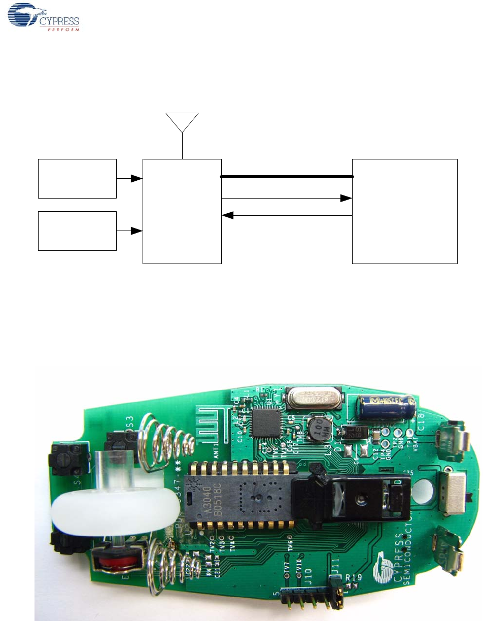
Figure 3-4. Printed Circuit Assembly (PDC-9347)
Figure 3-4 is a picture of the controller board with the PRoC LP and optical sensor. The ‘wiggle’ trace
in the upper left is the antenna. This board has the option of adding pull up resistors and filtering
capacitors to the z-wheel and then powering the z-wheel with a separate GPIO pin on the microcon-
troller. J10 is a programming header. Either the ICE-Cube or the PSoC MiniProg may be used to pro-
gram the mouse microcontroller using this ISSP header. J10’s pin 1 is a double header as a
mechanism to isolate the programming voltage and the operating voltage. To enter a manufacturing
PRoC Optical sensor
SPI
O_nCS
Scroll Wheel
Buttons
O_ Motion
[+] Feedback