


CY4672 Reference Design Guide, Document # 001-16968 Revision ** 43
Mouse
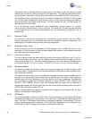
which it returns to the idle state. If the mouse is unable to deliver a packet while in this state, it transi-
tions to the disconnected state.
In idle state the optical sensor is allowed to transition through its various rest modes to conserve
power. In this state, the mouse application is waiting for input from the optical sensor, z-wheel or but-
tons. The timer is turned off to conserve power and the notion of time is maintained using the sleep
timer. This state is maintained indefinitely until the batteries drop below 1.8 volts at which point the
mouse enters the off state.
The off state is where the radio and optical sensor are prevented from turning on. This state is
reached when the battery voltage drops below 1.8 volts. It is designed to keep the battery drain to an
absolute minimum to prevent battery leakage as a result of completely draining the batteries.
The battery level is reported by the mouse application when it detects a change from the discon-
nected state to the connected state. The battery level is measured when exiting the idle state. If
there is a change in the battery level, it will be reported in the active state.
In the active state the mouse attempts to deliver a packet for the amount of time designated in
MOUSE_TX_TIMEOUT_MS. If it is unable to send the packet in this time, then it transitions to the
disconnected state.
The mouse application is responsible for detecting the Bind button press and then calling the bind
function in the protocol module; see Protocol Module on page 41.
The mouse application sends mouse reports as frequently as events arrive, but not any faster than
the time defined in the macro MOUSE_REPORT_IN_MS. Carefully set this time so that the report
rate does not exceed that which the USB bus is capable of handling. Keep in mind that the report
rate varies slightly due to drift of the internal oscillator used to keep track of time.
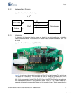
3.3.5.2 Optical Module
The optical sensor module encapsulates the initialization, calibration and reading of the optical sen-
sor. This module also handles any power management required by the sensor, along with motion
detection if supported. The contents of this module potentially change with every design and are
unique to the sensor used.
This module has the responsibility to format the X and Y data into the mouse packet payload. Refer
to section Wireless Protocol Data Payload on page 47 for a definition of the packet payload.
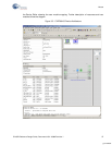
3.3.5.3 Testmode Module
The Testmode module provides code to continuously perform a vector drawing test within a drawing
application. This test mode is used to check radio range, co-location and interoperability of the
mouse with the keyboard.
The test mode, when compiled in, is entered by holding down the left and right button while inserting
the batteries. The buttons must be held down until the optical sensor begins to flash. As soon as the
buttons are released the mouse repeatedly draws ‘LP’ in the drawing application. Each successive
‘LP’ must be drawn on top of the previous one. The test mode may only be exited by removing the
batteries. All button presses and mouse movement are ignored when in the test mode. However,
care must be taken not to bump other mice connected to the PC.
Note The mouse ‘acceleration’ or ‘enhance pointer precision’ option needs to be turned off in the
Windows mouse Control Panel for this test to execute properly. If the letters are drawn erratically
with uneven sides or excessive amounts of space in between them, then check this setting or its
equivalent (based upon your PC operating system).
When the macro DEBUG_INDEX is defined, code is generated to move the mouse pointer to the
right and back again without the pen down. This is done in an incrementing fashion so that when
[+] Feedback