CY4672 Reference Design Guide, Document # 001-16968 Revision ** 49
Mouse
The second portion is the time between the start of the ISR and the post of the event flag. For exam-
ple, the motion interrupt takes 23 CPU clock cycles for this portion. Therefore, the Latency2 equals
to 1.917 µs for the 12 MHz CPU.
Consequently, the total latency for a motion interrupt is:
Latency1 + Latency2 = 4 µs
3.3.11 Code Performance Analysis
A mouse motion report is used to analyze the code performance. A typical mouse motion report con-
tains the following steps:
■ Optical sensor responds to a mouse motion. With the mouse the sensor in the rest 1 state, it
takes 16.5 ms for the sensor to responds to this sensor motion.
■ The sensor interrupts the MCU by lowering its motion pin. The prior section has calculated that it
takes 4 µs for MCU to respond to this Interrupt.
■ In the function timer_wait_event(), the MCU exits the sleep state and spends 53 µs to finish the
wheel poll.
■ Firmware delays MOUSE_REPORT_IN_MS, which is 10 ms for the default. This delay is to pre-
vent excessive radio retries from the mouse.
■ Firmware calls function mouse_do_report() to read the Delta_X and Delta_Y value and send the
packet to the bridge. This step takes 1.98 ms, which includes 1.66 ms radio transmission time.
As a result, if a mouse is in the rest 1 state, it takes 28.6 ms for the mouse to report a motion to a
bridge.
3.4 Development Environment
3.4.1 Tools
See the CY4672 Getting Started Guide for a list of tools required to build and debug the mouse
application.
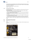
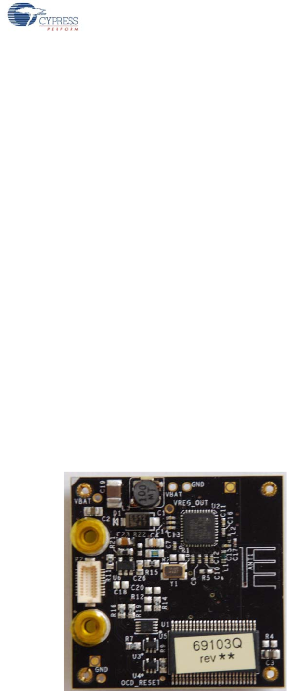
Figure 3-7. Pod Used for Debugging RDK Mouse
[+] Feedback


