


CY4672 Reference Design Guide, Document # 001-16968 Revision ** 77
Bridge
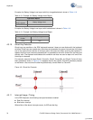
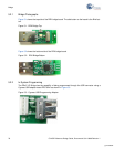
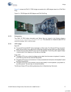
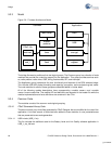
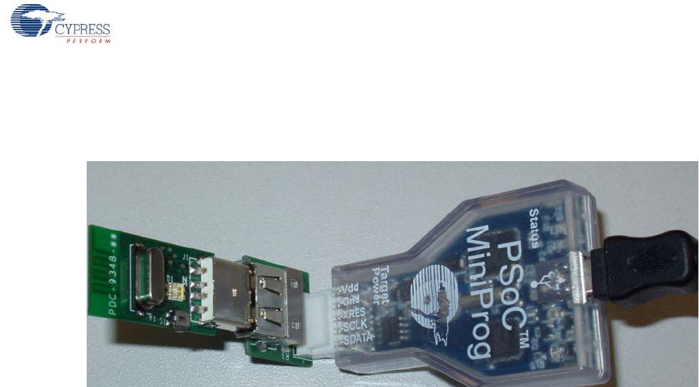
Figure 5-4 shows the PRoC LP RDK bridge connected with a USB adapter board to a PSoC Mini-
Prog.
Figure 5-4. RDK Bridge with USB Adapter and PSoC MiniProg
5.2.3 Schematics
The PRoC LP RDK bridge schematics and Gerber files are located in the following directory:
<installation directory>\Hardware\Bridge. The schematic is in Adobe Acrobat PDF for-
mat with the letters ‘Sch’ in the file name.
5.2.4 LED Usage
Red LED:
■ The red LED blinks ON/OFF when the bridge is in Bind mode. The ON and OFF time is approxi-
mately 320 ms which is the rate at which the bridge changes channels during the Bind process.
■ The red LED also blinks ON/OFF when the PC is suspended. The blinking rate is approximately
1 second which is the frequency of the wake up interrupts.
Green LED:
■ The green LED turns on when the bridge receives data from the mouse or keyboard. It remains
on for 250 ms since the last received Data packet.
■ The green LED turns on and remains on if a key is pressed and held (due to the keyboard’s send-
ing Keep Alive packets).
■ The green LED turns on and remains on during ping mode (in normal operation, ping mode is a
very short period. The user may not notice this period).
The Red and Green LED are blinking alternately when in Manufacturing Test mode.
[+] Feedback