


48 CY4672 Reference Design Guide, Document # 001-16968 Revision **
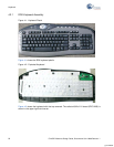
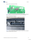
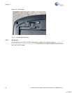
Mouse
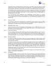
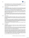
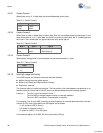
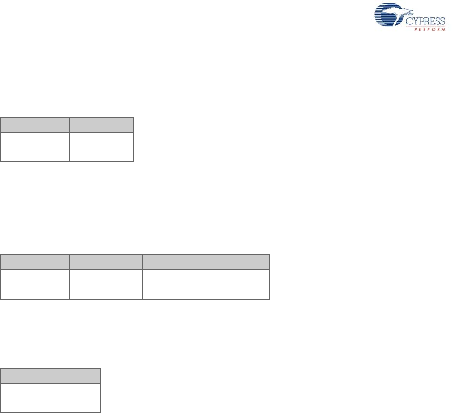
3.3.9.1 Packet Format 1
When there is only X, Y delta data, the transmitted packet is two bytes.
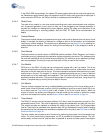
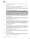
3.3.9.2 Packet Format 2
When there is either z-wheel data or button data, then the transmitted packet is three bytes. In the
case where there is no X, Y delta data, but there is z-wheel or button data, the X, Y delta bytes are
set to zero. The z-wheel data is a signed value with bit 4 as the sign bit.
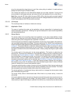
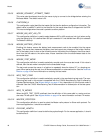
3.3.9.3 Packet Format 3
When battery voltage level is communicated, the transmitted packet is 1 byte.
3.3.10 Interrupt usage and timing
In the RDK mouse, the following interrupts has been enabled:
■ Motion interrupt from the optical sensor
■ Button (Left, Middle and Right buttons) interrupt
■ Bind button interrupt
The interrupt latency includes two portions. The first portion is the time between the assertion of an
enabled interrupt and the start of its ISR, which can be calculated using the following equation:
Latency1 = Time for current instruction to finish +
Time for M8C to change program counter to interrupt address +
Time for LJMP instruction in interrupt table to execute.
For example, if the 5-cycle JMP instruction is executing when an interrupt becomes active, the total
number of CPU clock cycles before the ISR begins are as follows:
(1 to 5 cycles for JMP to finish) +
(13 cycles for interrupt routine) +
(7 cycles for LJMP) = 21 to 25 cycles.
In the example above, at 12 MHz, 25 clock cycles take 2.083 µs.
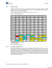
Table 3-3. Packet Format 1
Byte 1 Byte 2
X Delta
(8 bits)
Y Delta
(8 bits)
Table 3-4. Packet Format 2
Byte 1 Byte 2 Byte 3
X Delta
(8 bits)
Y Delta
(8 bits)
Buttons (Bits[7:5]),
Z Delta (Bits[4:0])
Table 3-5. Packet Format 3
Byte 1
Battery Level
(1 – 10)
[+] Feedback