


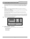
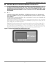
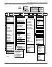

Advanced Microprocessor Controls Setup
12
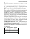
Standard Alarm Messages
• Water under floor
• Smoke detected
• Standby GC pump on
• Loss of water flow
• Standby unit on
For more information concerning alarms, see 6.0 - Alarm Descriptions and Solutions.
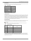
Humidity Control Method
The user may select between relative (direct) and absolute (predictive) humidity control. If relative is
selected, the RH control is taken directly from the RH sensor. If absolute is selected, the RH control is
automatically adjusted as the return air temperature deviates from the desired temperature setpoint.
This results in a predictive humidity control. The display will indicate % RH for both methods of con-
trol, but the adjusted humidity reading will be displayed if absolute is selected. With predictive
humidity control, the humidity control is automatically adjusted approximately 2% RH for each
degree difference between the return air temperature and the temperature setpoint.
With relative humidity control, unnecessary dehumidification can result when overcooling occurs dur-
ing a dehumidification cycle. This is because a higher than normal RH reading is caused by overcool-
ing the room (about 2% RH for each degree of overcooling). This extends the dehumidification cycle.
Later, when the dehumidification ends and the temperature rises to the setpoint, the RH reading
falls. The final RH reading will then be lower than actually desired. If the overcooling was significant
enough, the RH could be low enough to activate the humidifier.
If absolute humidity control is selected, over-dehumidification is avoided. When overcooling occurs,
causing an increase in the RH reading, the humidity control program “predicts” what the RH will be
when the dehumidification cycle ends and temperature returns to the setpoint. This allows the dehu-
midification cycle to end at the proper time. The predictive humidity control can reduce energy con-
sumption by minimizing compressor and reheat operation, and eliminating unnecessary humidifier
operation.
Analog Setup
For installation of analog sensors, see 5.0 - Response by Control Type—Advanced Microproces-
sor Controls.
After selecting a compatible sensor and properly wiring it to the terminals, set up the control to mon-
itor the sensor as follows:
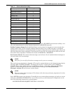
Slope: The slope is a multiplier used to scale the input signal. The slope can be positive (rising) or
negative (falling) and can range from 0 (resulting in a horizontal line) to ±999. The slope for a 0-5 volt
input is per 1 volt input, for 0-10 volt input is per 2 volt input, and for 4-20 mA is per 4 mA input. For
example, assuming an intercept of 0, for a 0-10 volt sensor input with a slope of 50, an input of 1 volt
would be displayed as 25: (1x[50/2]); 2 volts would be 50: (2x[50/2]); 3 volts would be 75: (3x[50/2]); etc.
Intercept: The intercept is an offset from point 0 corresponding to 0 volts or 0 mA input. The inter-
cept can be positive or negative and can be a point from 0 to ±999. Adding an intercept of 100 to the
slope example above, 1 volt would be 125: 100 + (1x[50/2]); 2 volts would be 150: 100 + (2x[50/2]); 3
volts would be 175: 100 + (3x[50/2]); etc.
Text: You may enter a custom label for each analog input. The text label can be 20 characters in
length including any of the following characters (or a blank space):
ABCDEFGHIJKLMNOPQRSTUVWXYZ#%*-0123456789
NOTE
For a 4-20 mA input sensor, if the desired reading at 4 mA input is 0, then an intercept of -1 x
slope would be required. For example, assuming a slope of 50, the formula would be ([-1 x 50] +
4 x [50/4]) = 0. The intercept is -50.