


Advanced Microprocessor Controls Setup
15
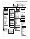
3.6 Main Menu (AM)—Status Display
The Status Display shows the present room temperature, humidity, active status functions (cooling,
heating, dehumidifying, humidifying), and active alarms. This is the data normally shown on the con-
trol screen. If no key is pressed for five minutes, the system automatically switches to the Status Dis-
play. The Status Display may also be selected from the Main Menu. While the Main Menu is
displayed, pressing the MENU/ESC key returns to the Status Display.
3.7 Load Control Features
3.7.1 Short Cycle Control
The control system monitors both compressors and prevents each from turning on within 3 minutes of
being turned off. If this (on, off, on) occurs too often, ten (10) times in one hour, a Short Cycle alarm
could occur.
3.7.2 Sequential Load Activation Control
The control allows only one load output to be energized at a time on a restoration of power or micro-
controller reset. Each additional load output will be activated at one second intervals until desired
operating conditions have been met.
3.7.3 Compressor Sequencing Control
The lead compressor is the first one to be turned on when compressor operation is required. The lag
compressor is turned on second if both compressors are required. The control monitors the operating
time of both compressors and will automatically switch lead/lag compressor operation to maintain
less than eight hours difference between the running times of two compressors.
When the operating hours on the lead compressor become eight hours greater than on the lag com-
pressor, the lead/lag operation is automatically switched. If the lead compressor is operating by itself
at that time, it will be turned off, the lead/lag operation will be changed, and the new lead compressor
will be turned on.
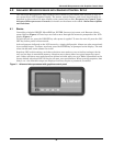
3.8 Control Circuit Board
The control circuit board is located inside the unit behind the LCD display and control key panel.
Open the front panel for access to the board.
The control board includes an adjustment for LCD display contrast, nonvolatile memory, DIP
switches (which should not require customer changes), control output LEDs and jumpers for board
configuration. The jumpers should be placed as follows:
P5—removed
P12—removed
P19—installed on Pins 1 and 2
P47—installed on Pins 1 and 2
P48—installed on Pins 1 and 2
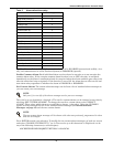
P50—all jumpers installed for 4-20 mA analog inputs. See Table 14 for other configurations
P51—removed
3.8.1 LCD Display Contrast
The level of contrast due to viewing angle of the LCD display can be adjusted using a small thumb
wheel at the upper left of the control board just under the cable going to the display. The control is
labeled R6.
NOTE
If the hot gas reheat option has been selected, compressor 2 is always the lead compressor.
NOTE
The LED backlighting on the text (4 x 20) display is always lit.