


Component Operation and Maintenance, Checks and Adjustments
62
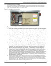
Circuit Board Adjustments
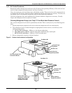
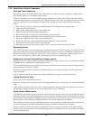
Humidifier operation is governed by the humidifier control board. This board is located in the lower
right area of the panel in the control section of the unit, or in the humidifier compartment on models
FH599C, 600C, 739C and 740C. There are two potentiometers mounted on the board. These pots can
be used to adjust for extreme water conductivity conditions and capacity.
The “%” pot controls the amperage at which the drain will energize. The pot is clearly marked in per-
centages. This adjustment is factory set, which indicates that the unit will drain when the amperage
falls off of the capacity setpoint. Raising the value increases the frequency of drain cycles. Lowering
the value decreases the frequency of drain cycles. The frequency should be increased for highly con-
ductive water and decreased for less conductive water. If adjustment is necessary, and a change of
three to four percent in either direction does not permit normal operation of the unit, consult your
Liebert supplier.
The pot marked “SEC” controls the duration of the drain cycle. The pot is clearly marked in seconds.
This adjustment is factory set at 60 (84) seconds and should not be readjusted without consulting your
Liebert supplier.
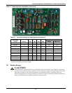
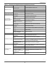
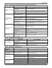
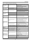
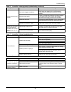
The DIP switches are used to set the capacity of the humidifier. These are preset at the factory and
should not be changed. Refer to Table 19 for the capacity of your unit. Find your unit voltage and
capacity in Table 20 to determine the correct DIP switch settings for your humidifier. A potentiome-
ter (R40) is used to regulate the capacity of the humidifier. This adjustment is factory set fully clock-
wise to 100%. It can be used to reduce humidifier capacity, but should never be used to raise the
capacity above the capacity for your model. Turn the adjustment counterclockwise to reduce your
capacity. The minimum setting is approximately 50% of the DIP switch setting.
!
WARNING
Circuit board adjustment should be performed by qualified personnel only. Hazardous
voltages are present in the equipment throughout the procedure. Use extreme caution. If
desired, power may be disconnected prior to the procedure.
NOTE
Numbers and percentages within parentheses ( ) in the following paragraphs refer to
circuit board settings for downflow models FH599C, 600C, 739C and 740C.
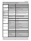
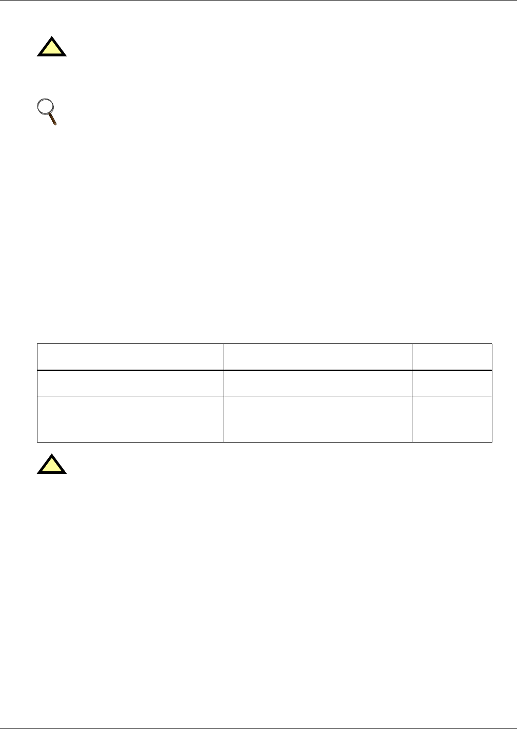
Table 19 Steam generating humidifier capacity
60 Hz Models 50 Hz Models
Capacity
lbs/hr (kg/hr)
75A, 72G, 86W, 114A, 110G, 127W, 125A,
116G, 138W, 147C, 200C, 248C
75A, 72G, 86W, 147C, 200C, 248C 11 (5)
199A, 192G, 219W, 245A, 240G, 267W,
290A, 265G, 315W, 380A, 363G, 412W,
302C, 376C, 422C, 529C, 600C, 740C
115A, 111G, 128W, 130A, 121G, 143W,
199A, 192G, 219W, 245A, 240G, 267W,
290A, 265G, 315W, 380A, 363G, 412W,
302C, 376C, 422C, 529C, 599C, 739C
22 (10)
!
CAUTION
The DIP switches must be set exactly as indicated in Table 20. Failure to correctly set the
DIP switches may result in an electrical or water hazard.