


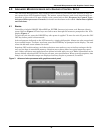


Advanced Microprocessor with Graphics Control Setup
22
4.4.4 Set Up Custom Alarms
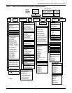
Selecting SETUP CUSTOM ALARMS will step to the following menu:
• SETUP CUSTOM ALARM TEXT
• CHANGE CUSTOM TEXT 1
• CHANGE CUSTOM TEXT 2
• CHANGE CUSTOM TEXT 3
• CHANGE CUSTOM TEXT 4
The custom alarm messages can be selected from a list of standard messages or you can write your
own messages. The message selected for any custom alarm can be changed at any time by selecting
SETUP CUSTOM ALARM TEXT. Five standard messages (see Standard Custom Alarm Mes-
sages below) and four custom messages are available to choose from. To modify the custom messages
press CHANGE CUSTOM TEXT 1 (2, 3 or 4). Each message can be up to 20 characters in length and
can be any of the following characters (or a blank space): ABCDEFGHIJKLMNOPQRSTU-
VWXYZ#%*-0123456789.
Standard Custom Alarm Messages
• WATER UNDER FLOOR
• SMOKE DETECTED
• STANDBY GC PUMP ON
• LOSS OF WATER FLOW
• STANDBY UNIT ON
For more information concerning alarms, see 6.0 - Alarm Descriptions and Solutions.
4.4.5 View Water Detect Floor Plan (for optional LTM1000/LT750)
When water is detected the alarm will sound and the WATER UNDER FLOOR alarm message will be
displayed. To see where the water is in the room, select VIEW/SET ALARMS from the Main Menu,
then VIEW WATER DETECT FLOOR PLAN. A tile will be highlighted and blinking to indicate the
position of the detected water.
4.4.6 Setup Water Detect Floor Plan
The water detection display is designed to graphically display the location of water under a raised
floor when connected to an LT750 water detection system. The selected (i.e., cursor) floor tile will be
highlighted and blinking. The UP and DOWN arrow keys are used to position the cursor tile. The UP
key will move the cursor tile up and then it wraps around to the bottom of the next column to the
right. The DOWN arrow key moves the cursor down, then to the top of the next column to the left. The
cursor will also wrap around from the right top tile to the left bottom tile and back.
There are three different types of tiles to be defined: the environmental unit, the LT750 and sensor
cable tiles. To set up the cable layout, first move the cursor to the location of the environmental unit
and press the ENTER key. A rectangular box will be drawn at that location. Then move the cursor to
the location of the LT750 and press the ENTER key. A solid circle will be drawn on the display. No
tile can have two definitions, so if the LT750 is physically directly under the unit, it has to be defined
at least one tile away.
The sensor cable should not be defined one tile at a time. The only sensor cable tiles that need to be
defined are the tiles where the cable is going to change direction, and the last tile. The display will
automatically define any tiles between two consecutively defined sensor tiles to be sensor tiles.
The ENTER key is also used to undo tile definitions. If a tile is defined in the wrong place, position
the cursor on that tile and press the ENTER key. It will undefine the tile under the cursor and move
the cursor back to the last defined tile. The entire layout can be erased by successively pressing the
ENTER key. When the last tile is defined, press the ESCape key to leave the setup screen.
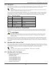
Installation—LT750 DIP Switch Settings
Install the LT750 following the instructions in the LT750 Users Manual. The following additional
switch selections should be made when connecting to an Advanced Microprocessor control:
DIP SW3-4 Off-(water alarm relay energizes for alarm)
DIP SW3-5 Off-(cable fault relay energizes for alarm)
Switch 1 - Off-(LT750 sources power for 4-20 mA loop)