


Advanced Microprocessor Controls Setup
16
3.8.2 Nonvolatile Memory
All critical information is stored in nonvolatile memory. Setpoints, setup parameters, and component
run hours are kept inside the microcontroller in EEPROM. Information retained for the alarm history
is kept in non-volatile RAM.
3.8.3 DIP Switches
Equipment options are selected and enabled using DIP switches 1 to 7. These are located at the upper
left of the control board and are labeled SW1. Switch 1 is at the top. These switches are factory set
and should not require any user changes. The setting and function of the switches can be read from
the LCD display and are also described in more detail in 4.8.4 - DIP Switches.
3.8.4 Control Outputs
Active control outputs are indicated with LEDs on the lower section of the control board. Each LED is
lit if the control output is active (on). The LEDs assist in troubleshooting the system.
3.9 Communications
The control system uses a two-wire, RS-422 channel to communicate with remote monitoring systems
via Liebert Site Products. This communication, directly out of the control, uses a proprietary protocol.
Your unit can have a variety of different Site Product devices wired to this port depending on the
monitoring system you are using.
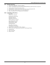
Liebert Site Product Device
• SiteScan Centralized Monitoring System—Stand-alone facility monitoring system
• SiteLink BMS Interface Module—For Modbus or BACnet communication to a third party moni-
toring system
• OpenComms Network Interface Card—For Ethernet connection using SNMP protocol
• OpenComms D.O. Interface Card—For discrete outputs of status and alarm conditions
• Mini-Remote—Stand-alone individual unit remote monitor
• ECA2 Communication Adapter—For remote service monitoring directly or via a modem
Consult the user manual of the appropriate device for specific installation and operation information.
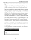
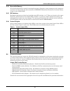
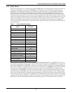
Table 6 Control output LEDs
LED Control Output
R5 Heat Rejection
LLSV1 Liquid Line Solenoid Valve 1
HGBP1 Hot Gas By-Pass or Compressor Unloader Valve
C1 Compressor 1
C2 Compressor 2
RH1 Reheat Stage 1 or Hot Gas Reheat Solenoid
RH2 Reheat Stage 2
RH3 Reheat Stage 3
HUM Humidifier
HGBP2 Hot Gas Bypass 2 or Compressor Unloader Valve 2
FAN Main Fan
HMV Humidifier Make-Up Valve
LLSV2 Liquid Line Solenoid Valve 2