


Response by Control Type—Advanced Microprocessor Controls
40
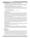
5.4 Analog Sensors
5.4.1 Connecting the Analog Sensors
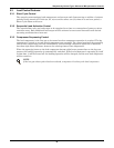
The sensor inputs are factory-set to accept a 4 - 20 mA signal. The inputs can be changed by removing
the appropriate jumpers on the control circuit board. See Table 13, Figure 5 and Figure 6.
The user supplied analog sensors MUST have their own power supply. To reduce the effects of inter-
ference from any noise source, the sensor input wiring should be shielded twisted pair and the shield
tied to earth ground at one end.
Analog input terminals for field connections are factory wired to the microprocessor board if specified
when ordered. Eight terminals are located in the field wiring compartment of the unit. Wire sensors
to the terminals as follows:
Consult your Liebert supplier for a field installation kit to add these connections after, if required.
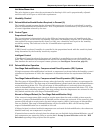
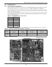
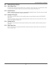
Figure 5 Analog input jumpers
Table 13 Changing factory-set sensor inputs
Terminal Signal
41 Input #1 (+)
42 Input #1 (-)
43 Input #2 (+)
44 Input #2 (-)
45 Input #3 (+)
46 Input #3 (-)
47 Input #4 (+)
48 Input #4 (-)
Table 14 Additional connections available after unit delivery
Input #1 Input #2 Input #3 Input #4
4–20 mA
Jumper P50.1&2 and
P50.3&4
Jumper P50.5&6 and
P50.7&8
Jumper P50.9&10 and
P50.11&12
Jumper P50.11&14 and
P50.15&16
0–5 VDC Jumper P50.1&2 Jumper P50.5&6 Jumper P50.9&10 Jumper P50.13&14
0–10 VDC
No jumper on
P50.1&2 and P50.3&4
No jumper on
P50.5&6 and P50.7&8
No jumper on
P50.9&10 and P50.11&12
No jumper on
P50.11&12 and P50.15&16
Analog input jumper location
ENLARGED AREA