


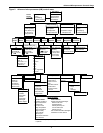

Advanced Microprocessor Controls Setup
13
Set Status Display
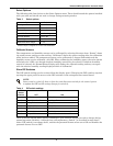
The Status Display can be set to show the return air temperature and humidity SENSOR READ-
INGS or the temperature and humidity control SETPOINTS through this selection. When SET-
POINTS is selected, the status display indicates so by displaying “SETPTS.” If SENSOR READINGS
is selected, the Status Display will show the return air sensor readings.
Calibrate Actuator
For systems that use a valve actuator for chilled water or glycol cooling, the actuator timing may be
calibrated or adjusted. This is the time it takes for the valve to travel from full closed to full open. It is
programmable from 0 to 255 seconds. The factory default time is 165 seconds and should not be
changed unless the actual valve travel time is not correct. The full valve travel time is used by the
control to determine the appropriate valve position. For example, if the valve travel time is 165 sec-
onds and 50% cooling is being called for, the valve will open for 83 seconds to achieve 50% open. To
change the valve travel time, first enter the CALIBRATE ACTUATOR screen. The display will show
the present period used by the control for valve actuator full travel. Press ENTER and adjust the time
using the UP/DOWN arrows. When the correct time is displayed, press ENTER to store the new time
in memory.
3.4.3 Run Diagnostics
From the Run Diagnostics menu, maintenance personnel can check system inputs, outputs, and com-
plete a test of the microcontroller circuit board, all from the front panel. Review of the system inputs
and the microcontroller test can be done without interrupting normal operation. To test the system
outputs, the normal system control is temporarily suspended. DO NOT leave the unit in the diagnos-
tics mode any longer than is necessary for troubleshooting. The control system will return to normal
operation in 5 minutes, automatically, if no key is pressed.
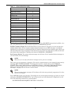
Show Inputs
With the unit on and the fan running, the input state for the following devices may be displayed:
• Air sail switch: normally off unless Loss of Air Alarm is active
• Custom alarm #1: normally off unless this alarm is active
• Custom alarm #2: normally off unless this alarm is active
• Custom alarm #3: normally off unless this alarm is active
• Custom alarm #4: normally off unless this alarm is active
• Humidifier problem: normally on unless this alarm is active
• Filter clog: normally off unless Change Filters Alarm is active
• Main fan overload: normally on unless Main Fan Overload Alarm is active
• High Head Comp 2: normally off unless High Head Pressure Alarm Compressor 2 is active
• Comp 2 Overload: normally on unless Compressor 2 Overload Alarm is active
• Shutdown device: normally on unless unit is off through the Fire Stat or Remote Shutdown
Device
• Low press switch 2: normally on if compressor circuit 2 is in operation
• Low press switch 1: normally on if compressor circuit is in operation
• Comp 1 Overload: normally on unless Compressor 1 Overload Alarm is active
• High Head Comp 1: normally off unless High Head Pressure Alarm Compressor 1 is active