


Response by Control Type—Advanced Microprocessor Controls
41
5.4.2 Water Detection Display
The water detection display is designed to graphically display the location of water under a raised
floor when connected to an LT750 water detection system. The graphical floor plan screen shows a
30 x 16 grid. Each square represents one standard floor tile (approximately 2 ft. x 2ft.).
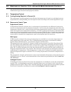
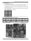
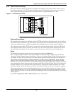
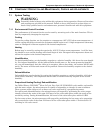
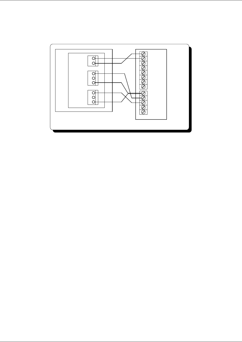
Figure 6 Connecting the LT750
Physical Connections
The example above shows the 4-20 mA output of LT750 connected to Analog Input #1 (41 and 42) on
the external inputs terminal strip. This strip is provided on units ordered with analog inputs. (If this
strip is not installed, there is a field installation kit available from your Liebert representative.)
The 4-20 mA output of the LT750 must be connected to the first analog input, as shown. TB4 is the
water detected relay output. It can be connected to any one of the four special alarm inputs. TB5 is
the cable fault relay output. It can also be connected to any one of the four special alarm inputs.
Setup
The following description assumes wiring connections as shown in Figure 6.
First, verify that special alarms 1 and 2 are Enabled to either Warning or Urgent type. Do this by
selecting View/Set Alarms from the Main Menu. Then, select Setup Alarms. Follow the instructions on
the display to select the required type for Custom Alarm #1 and Custom Alarm #2 if not already set.
Next, select the alarm message for Custom Alarm #1 and #2. From the Main Menu, select View/Set
Alarms. Then, select Setup Custom Alarms. Then, select Setup Custom Alarm Text. Define Custom
Alarm #1 to be Custom 1. (Custom 1 is the default message that will be displayed if a message has never
been programmed.) Next, select the text for custom alarm #2 to be Water Under Floor. Now, change the
message Custom 1 to LT750 Cable Fault. This is done by selecting the Change Custom Text 1 menu
item in the Setup Custom Alarms menu. Follow the instructions on the screen to change the message.
The slope and intercept values of Analog Input #1 are used to calculate the location of water. These
values should initially be set to zero. The default values are zero, but it may be a good idea to verify
those values. They can be viewed by selecting Analog/Digital Inputs from the Main Menu, then Setup
Analog Inputs.
See 4.4.6 - Setup Water Detect Floor Plan for more information.
Environmental Unit
24
50
51
55
56
41
42
43
44
45
46
47
48
LT750
NO
NC
C
NO
NC
C
-
+
1
2
1
2
3
1
2
3
TB6
TB5
TB4
fault
water