


Component Operation and Maintenance, Checks and Adjustments
51
7.3.3 Electronic Variable Speed Drive (Inverter)
On large Deluxe chilled water models an optional variable speed drive inverter is available. This
packaged unit is factory set and should not require field adjustments. The variable speed drive saves
power by reducing blower speed to match unit load. If you suspect a problem with the inverter, first
make sure that the INTELLIGENT CONTROL method is selected at the microprocessor.
1. TURN OFF ALL POWER TO THE UNIT AT THE DISCONNECT.
2. Open the unit accent panel and electric box cover.
3. Find the main fan motor wires. These are connected to the motor overload relay in the
high-voltage section of the electric box.
a. Mark motor wires to ensure they can be reconnected in the same order.
b. Disconnect motor wires at the load side of the motor overload relay.
c. Close the electric box cover.
4. Remove the right front vertical panel to gain access to the variable speed drive.
5. With the panel removed, restore power to the unit by turning the disconnect on.
6. Consult the factory for instructions on unlocking the keypad—the keypad is locked after factory
programming of the variable speed drive parameters.
7. Consult the variable speed drive operation manual for instructions on accessing and changing the
desired parameter settings.
8. Place the right front vertical panel back on the unit.
9. Reconnect the motor wires to the overload and close the electric box cover and unit accent panel.
10. Restore power at the disconnect
7.4 Refrigeration System
Each month the components of the refrigeration system should be inspected for proper function and
signs of wear. Because evidence of malfunction is usually present prior to component failure, periodic
inspections can be a major factor in the prevention of most system failures.
Refrigerant lines must be properly supported and not allowed to vibrate against ceilings, floors, or the
unit frame. Inspect all refrigerant lines every six months for signs of wear and proper support. Also
inspect capillary and equalizer lines from the expansion valve and support as necessary.
Each liquid line has a sight glass that indicates liquid refrigerant flow and the presence of moisture.
Bubbles in the sight glass indicate a shortage of refrigerant or a restriction in the liquid line. The
moisture indicator changes from green to yellow when moisture is present in the system.
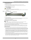
7.4.1 Compressor Oil Level
There is a glass “bull’s eye” provided on each compressor (clearly visible when the end door is open)
that permits viewing the oil level.
Normally, the oil level should be 1/2 to 3/4 up from the bottom of the sight glass. However, this level
may vary during operation due to the action of the moving parts. When idle, the oil level may be
higher due to absorption of the refrigerant.
After a compressor has been idle for an extended length of time, foaming will usually be present when
the compressor first starts. Wait until the compressor has been operating for at least five minutes
before viewing the oil level.
Refrigeration oil does not deteriorate with normal usage and does not need to be changed unless it
becomes discolored or acidic. Periodically inspect the compressor compartment for signs of oil leakage.
If a leak is present, it must be corrected and the oil level returned to its proper level using Sunisco
3GS refrigerant oil. Take new oil from sealed containers opened at the time of use. Oil exposed to air
will absorb moisture.
!
WARNING
For operator safety, the variable speed drive must not be programmed while power is
connected to the motor.
Read all instructions before proceeding.
Only qualified service technicians should make changes to the variable speed drive
programming.