


Alarm Descriptions and Solutions
44
6.0 ALARM DESCRIPTIONS AND SOLUTIONS
The Advanced Microprocessor (AM) and the Advanced Microprocessor with Graphics (AG) Control
systems will audibly and visually annunciate all Enabled alarms, including the four (4) custom
alarms. With the AM & AG Controls, the customer alarms can be from the optional alarm list and/or
can have their own fully custom text. Two (2) alarms may be selected as custom for AM and four (4)
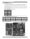
can be custom for AG. The custom alarm inputs are 24 Volts AC which is available from the Liebert
unit. Alarms are wired from terminal 24 through a normally open contact to locations 50, 51, 55, and
56, respectively, for alarms 1 through 4.
The AM and AG alarms can be delayed from 0 to 255 seconds (see Setup Alarms on page 10). The
AM alarms can be Enabled or Disabled (also in Setup Alarms on page 10). Also, the AM alarms can
be programmed to energize the Common Alarm Relay or to “alarm only” and not energize the Com-
mon Alarm Relay.
The AG alarms can be selected as Warning, Urgent, or Disabled. If selected to be a Warning, they are
annunciated after the Time Delay but do not energize the Common Alarm Relay. If selected as
Urgent, they are annunciated after the Time Delay as a Warning alarm and then re-annunciated
after a user programmable period from 0 minutes to 999 hours as an Urgent alarm. When annunci-
ated as an Urgent alarm, the Common Alarm Relay is activated. The custom alarm inputs of the AG
can be designated “Status Only.” As Status Only, the custom alarm input is referenced as a digital
input and is no longer treated as an alarm. It is for monitoring only and can be reviewed by selecting
“Analog/Digital Inputs.”
When a new alarm occurs, it is displayed on the screen and the audible alarm is activated. If commu-
nicating with a Liebert Site Product, the alarm is also transmitted. The display will also show a mes-
sage to “Press Enter Key to Silence” the alarm. After the alarm is silenced, the display will return to
the Normal Status Display. For the AG, the bell and hammer are shown at the top of the Normal Sta-
tus Display. For the AM, the bottom line will display the number of Active Alarms. For the SM, the
alarm is displayed by a lighted LED next to the alarm text. The active alarms can be reviewed on the
Advanced Microprocessor Controls by selecting “Active Alarms.”
The alarms can also be silenced through communications with a Liebert Site Products unit. Most
alarms will reset automatically when the alarm condition is no longer present and only after it has
been acknowledged by being “Silenced.” The exceptions are:
a. The three software alarms: Loss of Power, Low Suction Pressure, and Short Cycle which reset
automatically 90 minutes after being “Silenced” or acknowledged.
b. (2) Some alarms such as overloads and high pressure switches may require a manual reset
depending on your model.
A history of the alarms (10 for AM units and 60 for AG units) is retained in nonvolatile memory (for
AM information, see 3.3.3 - Alarm History Log; for AG information, see 4.4.2 - Alarm History Log).
This section provides a definition of each available alarm. Troubleshooting suggestions are included.
Refer to 8.0 - Troubleshooting for more details. If you need assistance with your environmental con-
trol system, contact your Liebert supplier.
6.1 Standard Alarms
6.1.1 Change Filter
Periodically, the return air filters in the environmental units must be changed. The Change Filter
alarm notifies the user that filter replacement is necessary. A differential air pressure switch closes
when the pressure drop across the filters becomes excessive. The switch is adjustable using the proce-
dure on the switch label.
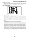
6.1.2 Compressor Overload
The control break compressor safety stats located internal to the Carlyle compressors are tripped
when an overload condition occurs. When a Copeland compressor is used, an optional tri-block over-
load device can be used for each compressor. Compressor overload may be manual or automatic reset,
depending on your model. Overload is located at the electric connection box on the compressor. Note
that compressor #1 is the top compressor and compressor #2 is the bottom one.