


Advanced Microprocessor with Graphics Control Setup
32
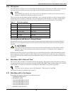
4.14.4 Control Outputs
Active control outputs are indicated with LEDs on the lower section of the control board. Each LED is
lit if the control output is active (on). Use these LEDs to assist in troubleshooting the system.
4.15 Communications
The control system uses a two-wire, RS-422 channel to communicate with remote monitoring systems
via Liebert Site Products. This communication, directly out of the control, uses a proprietary protocol.
Your unit can have a variety of different Site Product devices wired to this port depending on the
monitoring system you are using.
Liebert Site Product Device
• SiteScan Centralized Monitoring System—Stand alone facility monitoring system
• SiteLink BMS Interface Module—For Modbus or BACnet communication to a third party moni-
toring system
• OpenComms Network Interface Card—For Ethernet connection using SNMP protocol
• OpenComms D.O. Interface Card—For discrete outputs of status and alarm conditions
• Mini-Remote - Stand alone individual unit remote monitor
• ECA2 Communication Adapter—For remote service monitoring directly or via a modem
Consult the User Manual of the appropriate device for specific installation and operation information.
4.15.1 Monitor functions:
1. Temperature/Humidity: Present readings
2. Status: Cooling/Heating and Humidifying/Dehumidifying operating status in percent
3. Present Alarms: Alarms presently active
4. Alarm History: 10 most recent alarms (60 most recent alarms for AG)
5. Run Time Log: Operating hours on major components
6. Daily Log: High and Low Temperature & Humidity
4.15.2 View/Change Functions:
2. Control Type: Proportional, PID, Intelligent
3. PID Parameters: Proportional, Derivative and Integral Gains
4. On/Off Status
5. Time: View Only
6. Silence Alarm
Table 12 Control output LEDs
LED Control Output
R5 Heat Rejection
LLSV1 Liquid Line Solenoid Valve 1
HGBP1 Hot Gas By-Pass or Compressor Unloader Valve
C1 Compressor 1
C2 Compressor 2
RH1 Reheat Stage 1 or Hot Gas Reheat Solenoid
RH2 Reheat Stage 2
RH3 Reheat Stage 3
HUM Humidifier
HGBP2 Hot Gas Bypass 2 or Compressor Unloader Valve 2
FAN Main Fan
HMV Humidifier Make-Up Valve
LLSV2 Liquid Line Solenoid Valve 2
1. Setpoints:
Temperature Setpoint High Humidity Alarm
Temperature Sensitivity Low Humidity Alarm
Humidity Setpoint Cold Start Delay
Humidity Sensitivity Humidifier Flush Rate
High Temperature Alarm Chilled Water Flush Rate
Low Temperature Alarm