


Response by Control Type—Advanced Microprocessor Controls
42
Calibration
Calibration should not be required for most installations. The accuracy of this display is approxi-
mately 1%.
The display is calibrated by the slope and intercept values of Analog Input #1. The position of the
water is calculated from the analog output of the LT750 using the formula:
position = analog reading/full scale reading X (measured length + slope) + intercept
position is the distance from the LT750 to the position of the detected water.
measured length is the length of the cable which is calculated automatically when the layout is
defined. The units for these values are in floor tiles.
The intercept value read from Analog Input #1 is added to the measured position of a water indication
to determine which tile to highlight. For example, if water is displayed under the seventh tile but
determined to be under the fifth tile, set the offset value to -2 tiles. Use the intercept value to correct
errors close to the start of the cable.
Accuracy errors farther out on the cable should be corrected using Analog Input #1's slope value. This
value effectively adjusts the measured length of the cable. Increasing the effective length of cable will
increase the distance of the water and move the highlighted tile farther along the cable, and vice
versa. Unlike the intercept, which adjusts by the same amount for all locations on the cable, the slope
increases its effect for larger distances.
The best procedure to calibrate the cable would be to first simulate water close to the LT750, about 5
tiles out. Adjust the intercept to get the correct reading. Next, simulate water 5 tiles from the end.
Adjust the slope to get the correct reading.
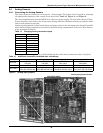
5.5 Communications
The control system uses a two-wire, RS-422 channel to communicate with remote monitoring systems
via Liebert Site Products. This communication, directly out of the control, uses a proprietary protocol.
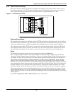
Your unit can have a variety of different Site Product devices wired to this port depending on the
monitoring system you are using.
Liebert Site Product Device
• SiteScan Centralized Monitoring System—Stand alone facility monitoring system
• SiteLink BMS Interface Module—For Modbus or BACnet communication to a third party moni-
toring system
• OpenComms Network Interface Card—For Ethernet connection using SNMP protocol
• OpenComms D.O. Interface Card—For discrete outputs of status and alarm conditions
• Mini-Remote - Stand alone individual unit remote monitor
• ECA2 Communication Adapter—For remote service monitoring directly or via a modem
Consult the User Manual of the appropriate device for specific installation and operation information.
5.5.1 Monitor functions:
1. Temperature/Humidity: Present readings
2. Status: Cooling/Heating and Humidifying/Dehumidifying operating status in percent
3. Present Alarms: Alarms presently active
4. Alarm History: 10 most recent alarms (60 most recent alarms for AG)
5. Run Time Log: Operating hours on major components
6. Daily Log: High and Low Temperature & Humidity