


Component Operation and Maintenance, Checks and Adjustments
61
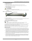
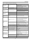
11. The canister is now ready to be removed.
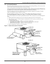
On the downflow chilled water units: Slide the humidifier cabinet bottom straight out toward you
and drop the canister through the bottom of the cabinet.
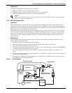
On all other units: Pull the canister straight out of the cabinet toward you.
12. Replace the canister with the part indicated in the following table.
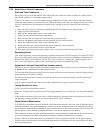
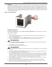
13. Replace the canister by reversing the above procedure. Make special note of the following:
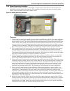
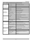
Fault Descriptions
Overcurrent—Operating current exceeds present limit
Fill Valve—Continuously energized valve exceeds preset limit
End of Life—Drain count limit exceeded in a 24-hour period
Fail to Make Capacity—Does not reach operational current within initial 24 hours
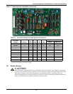
Test Points
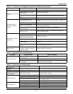
Table 17 Humidifier canister part numbers
Unit Model Part Number Voltage
Capacity
lbs/hr kg/hr
All except below
200-230 380-575* 11 or 22 5 or 10
153315P1 153315P2
FH599C, 600C, 739C, 740C 136799P1 200-480 22 10
FH599C, 600C, 739C, 740C 136799P2 575 22 10
*Note: 575 V units have a step-down transformer included with unit
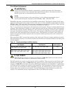
!
CAUTION
When reconnecting the power wiring, follow exactly the instructions included with kit
153315P1 and P2 or the unit electrical schematic with canisters 136799P1 and P2.
NOTE
When replacing the canister, always check the fill and drain solenoids for proper operation.
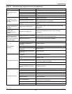
Table 18 Faults—canister generator humidifier
Priority Name LED Indication Description
1 Over Current Solid Humidifier Lockout
2 Fill Valve 2 second flash Humidifier Lockout
3 End of Life 4 second flash Humidifier Lockout
4 Fail to Make Capacity 1 second flash Indicate only
TP1—Time Cycle Pot 1 VDC = 60 seconds
TP2—Low Drain Pot 3 VDC = 80%
TP3—Capacity Pot 3.5 VDC = 85%
TP5—RT Capacity 1 VDC = 100%