


WARNING
THERE MUST NOT BE ANY OPENINGS BETWEEN THE
BLOWER DIVISION PANEL AND THE COMBUSTION
COMPARTMENT. THE BLOWER COMPARTMENT IS UNDER
GREATER SUCTION THEN THE COMBUSTION
COMPARTMENT AND CAN PULL COMBUSTION AIR FROM
THE BURNERS AND CAUSE INCOMPLETE COMBUSTION
AND ERRATIC FURNACE OPERATION.
W
ARNING
THE VENT MUST BE CLAMPED TO THE FURNACE PANEL
USING THE GASKET AND CLAMP PROVIDED.
THE INTAKE MUST USE THE THREADED PVC
CONNECTOR WITH THE GASKET AND LOCK NUT.
Keep pressure switch hose above heat exchanger drain
and exhaust port.
IMPORTANT
If the pipe and fittings are to be other than PVC, use
the proper cleaner, primer and cement for the
dissimilar materials.
IMPORTANT
If the pipe is increased in size with a reducer it must
be on a vertical section of the pipe to facilitate drain-
ing the vent. Reducing the size of pipe to exit the
IMPORTANT
Always secure or support the exhaust vent and
combustion air inlet piping to the floor joists or rafters
to avoid sagging and possible fatigue of venting
materials. This ensures proper drainage and
preventing spilling of the products of combustion into
the building.
IMPORTANT
C
lean and de-burr all pipe cuts. The shavings must not
be allowed to block the exhaust, combustion air inlet
o
r condensate drain lines.
IMPORTANT
8
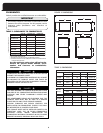
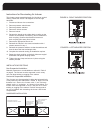
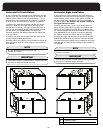
INSTALLATION POSITIONS
T
he furnace can be installed in any of four positions:
• Upflow
• Downflow
• Horizontal left
• Horizontal right
M
aintain clearances to combustibles as outlined in Table 2.
Support the furnace cabinet to prevent twisting or
sagging.
General Considerations
When choosing an installation position the installer must
consider the following connections:
• Combustion air intake
• Exhaust vent
• Gas pipe
• Electrical wiring
• Condensate drain trap
Also consider the air conditioning connections, a/c drain,
access to filter(s) and access to furnace and a/c for repair.
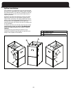
The blower compartment should be completely isolated
from the burner compartment. In tight rooms with other
combustion devices, the blower compartment must be
completely isolated from the room. The combustion
compartment must also be completely isolated from the
room (unless non-direct vent). Sometimes the knockout
tool will punch too deep and open holes. Use caulking on
the inside of the cabinet to seal any holes. Insure that the
combustion door gasket is in good condition.
Drains and traps of furnaces installed in spaces
subjected to freezing temperature must also be
protected against freezing.
IMPORTANT
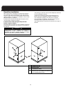
Exhaust V
ent Connection
The exhaust vent must be clamped to the exterior panel(s)
with the clamp provided. Place the gasket between the
clamp and the side panel. Tighten clamp and fasten in
place using the three screws provided.
The clamp should secure the vent pipe to prevent internal
damage if the vent pipe is tampered with.
Combustion Air Inlet Connection
The combustion air inlet fitting is a 2” PVC Socket to Pipe
Thread adapter. Chose the intake location and open the
appropriate knock out. Install the adapter to the exterior
p
anel using the gasket on the outside of the panel and the
locknut on the inside of the panel.
reducer can be on the horizontal.
house (as shown on page 19, Figures 4 and 6), the