


WARNING
READ AND FOLLOW ALL INSTRUCTIONS IN THIS SEC-
TION. FAILURE TO PROPERLY VENT THIS FURNACE CAN
CAUSE CARBON MONOXIDE POISONING OR AN EXPLO-
SION OR FIRE RESULTING IN PROPERTY DAMAGE, PER-
SONAL INJURY OR LOSS OF LIFE.
Definitions
"Vent" and "Chimney" refer to open passageways that
convey vent gases from the furnace, or its vent connector, to
the outside. Vents and chimneys usually run vertically or
nearly vertically. When they serve only one gas appliance,
they are called "dedicated" vents or chimneys. When they
serve multiple gas appliances, they are called "common"
vents or chimneys.
"Vent Connector" refers to a pipe or duct that connects the
furnace to a vent or chimney. Vent connectors usually run
from the furnace’s vent collar to the vent or chimney. Vent
connectors may have vertical and horizontal runs.
"Venting System" refers to a continuous open passageway
from the vent collar to the outside. Venting systems usually
have a vent connector(s) and a vent or chimney
. V
enting
systems commonly serve a single furnace, or a single
furnace and a hot water heater
. Other multiple appliance
venting systems are less common.
"Fan Assisted Combustion System" refers to an appliance
equipped with an integral mechanical means to either draw
or force products of combustion through the combustion
chamber and/or heat exchanger. This series furnace uses a
draft inducer to draw combustion products through the
heat exchanger and is considered to have a fan assisted
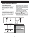
combustion systems must not be vented into single wall
metal vents.
WARNING
NEVER ALLOW THE PRODUCTS OF COMBUSTION FROM
THE FLUE TO ENTER THE RETURN AIR OR SUPPLY AIR
D
UCTWORK.
ALL RETURN AIR DUCTWORK MUST BE ADEQUATELY
SEALED AND SECURED TO THE FURNACE WITH SHEET
M
ETAL SCREWS. TAPE THE SHEET METAL SEAMS IN THE
VICINITY OF THE FURNACE WITH DUCT TAPE OR
SIMILAR MATERIAL.
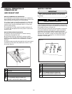
WHEN THE FURNACE IS MOUNTED ON A PLATFORM
WITH RETURN AIR THROUGH THE BOTTOM, IT MUST BE
SEALED AIR TIGHT BETWEEN THE FURNACE AND THE
RETURN AIR PLENUM. THE FLOOR OR PLATFORM MUST
PROVIDE SOUND PHYSICAL SUPPORT OF THE FURNACE
WITHOUT SAGGING, CRACKS OR GAPS AROUND THE
BASE, PROVIDING A SEAL BETWEEN THE SUPPORT AND
THE BASE.
FAILURE TO PREVENT PRODUCTS OF COMBUSTION
FROM BEING CIRCULATED INTO THE LIVING SPACE CAN
CREATE POTENTIALLY HAZARDOUS CONDITIONS,
INCLUDING CARBON MONOXIDE POISONING THAT
COULD RESULT IN PERSONAL INJURY OR DEATH.
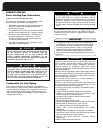
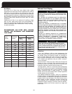
TABLE F
RECOMMENDED AIR FILTER AREA (SQUARE INCHES),
FOR DISPOSABLE AND PERMANENT TYPE FILTERS
COOL
(TONS)
AIR FLOW
(SCFM)
AREA
(INCH
2
)
AREA
(INCH
2
)
1.5
2
2.5
3
3.5
4
5
650
810
1000
1150
1350
1550
1750
312
389
480
552
648
744
840
156
194
240
276
324
372
420
919
1226
1532
1839
441
588
735
883
221
294
368
441
HEAT INPUT
(BTU/HR)
54,000
72,000
90,000
108,000
RECOMMENDED AIR FILTER AREA (SQUARE
INCHES), FOR DISPOSABLE AND PERMANENT
TYPE FILTERS
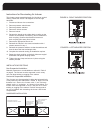
Air Filters
IAQ types of air filters may cause higher static, higher
temperature rise and erratic furnace operation and, with an
ECM drive, can cause blower over speed more noise. Also
t
he consumer may at some time want to add UV treatment,
a
nd electrostatic air cleaners or HEPA filters. Thus the return
duct should be sized larger than traditionally and also more
clearance space allow around the return duct for future
e
quipment.
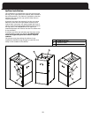
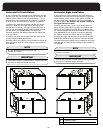
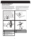
Angling the air filter is one method of installing a larger
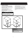
Exhaust Vent Piping
15
combustion system. Category I furnaces with fan assisted
filter sizes. By examining the table one can see that many
in poorer air quality.
existing installations have undersized air filters, resulting
area air filter. Table below shows the recommended air
DISPOSABLE PERMANENT