


DISCONNECT THE ELECTRICAL POWER SUPPLY TO THE
FURNACE BEFORE ATTEMPTING THIS MAINTENANCE
PROCEDURE. FAILURE TO DO SO CAN CAUSE
E
LECTRICAL SHOCK RESULTING IN PERSONAL INJURY OR
L
OSS OF LIFE.
A
ll electrical connections should be examined to ensure that
they are tight and corrosion free. Repair any connections
that have become loose or corroded.
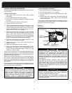
Furnace Operation
The furnace should be cycled during the annual inspection
and servicing to:
1. Test all safety related controls.
2. Determine that the temperature rise falls within the
range shown on the appliance rating plate.
3. Ensure that the burner ignition is smooth and that the
flames are smooth soft blue, and not impinging on the
heat exchanger.
Label all wires prior to disconnection when servicing
controls. Wiring errors can cause improper and
dangerous operation.
Always verify proper operation after servicing.
FIELD SUPPLIED AND INSTALLED OPTIONAL
ACCESSORIES
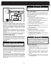
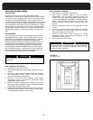
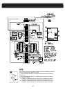
Electronic Air Cleaner
The integrated furnace control has provisions to supply
power and control an electronic air cleaner rated at 120vac,
1.0 amp max.
Line voltage for an electronic air cleaner may be picked up
from the "EAC-N". 120 volt power will be available at these
terminals whenever the circulating fan is operating in the
heating or cooling modes.
The integrated furnace control has provisions to supply
power and to control a line voltage humidifier or the
primary of a 120 / 24 volt humidifier step down transformer
,
rated at 120vac, 1.0 amp max.
Line voltage for a humidifier may be picked up from the
"HUM-H" terminal and from the "HUM-N" terminal. 120
volt power will be available at these terminals whenever
the circulating fan is operating in the heating mode.
Electrical
ALL WIRING INSIDE THE FURNACE MUST HAVE A
MINIMUM TEMPERATURE RATING OF 105C.
All HUM (humidifier) and EAC (electronic air cleaner)
terminals are 120v. Do not directly connect 24v
equipment to them.
IMPORTANT
All furnace and furnace accessory wiring shall conform
to the temperature limitations of 63
°F (35°C) rise.
IMPORTANT
WARNING
CAUTION
WARNING
heat and make a retrial for high every 5 or 10 minutes.
switch does not pull in the controller will continue in low
finished) and during the trial for ignition the high pressure
If there is a demand for high heat (low heat firing period is
The fourth scenario:
heat.
the gas low the flame noise sounds deceptively like high
heat should free it. Note: When the inducer is in high and
gas valve to low. If there is ice in the vent the continuous
period, the high pressure switch makes, the gas valve will
long as the low pressure switch is made). If, during this
switch, the unit will stay in low heat and high inducer (as
the next trial for high fails to make the high pressure
If the low heat fails after the warm-up period, and when
The third scenario;
for pressure switch failed to close.
exchanger drain tube the furnace will cycle and flash code
the igniter or gas on. If there is an air trap in the heat
voltage. If there is a blocked drain the furnace will not turn
a combination of high wind and long vent length and low
the failure of the low heat is temporary and may be due to
then after the warm-up period go to high heat. Most likely
controller will wait 3 minutes before ignition retrial and
If the low heat fails after the warm-up period, the
The second scenario;
inducer until the high pressure switch makes.
fails to make, the furnace will run in low gas and high
demand for heat is high and the high heat pressure switch
a single stage thermostat, or with a two stage T-stat the
• if, after the warm-up period and the low heat period with
Scenario one:
to supply heat in one of three alternate firing scenarios.
h
before high heat. If there is a problem with high or low
thermostat option, there is a selectable low heat period
or inducer to heat demand. With the single stage
and after a 60 second warm-up period adjusts either the gas
inducer (only the low pressure switch is required to make)
The controller ignites the furnace in low heat and high
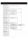
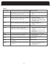
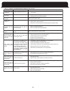
Troubleshooting
will aid in trouble shooting.
39
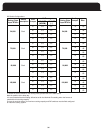
Page 41, Table 9, Page 42, Table 10 and Figure (trouble shooting)
eat the UTEC 1170-25 controller will attempt to continue
Humidifiers/ Electronic Air Cleaners
switch to high. A loss of high pressure switch will force the