


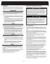
COMBUSTION AIR
EXHAUST
8”
12”
2”
12” CLEARANCE
ABOVE GRADE OR
HIGHEST ANTICIPATED SNOW LEVEL.
D
E
F
G
H
I
J
K
L
A
B
C
COMBUSTION AIR
EXHAUST
8”
12”
2”
12” CLEARANCE
ABOVE GRADE OR
HIGHEST ANTICIPATED SNOW LEVEL.
D
E
F
G
H
I
J
K
L
A
B
C
B
C
TOP VIEW
INTERIOR
EXTERIOR
C
D
J
A
B
I
A
B
E
D
C
F
H
A
E
E
D
B
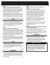
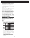
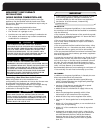
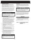
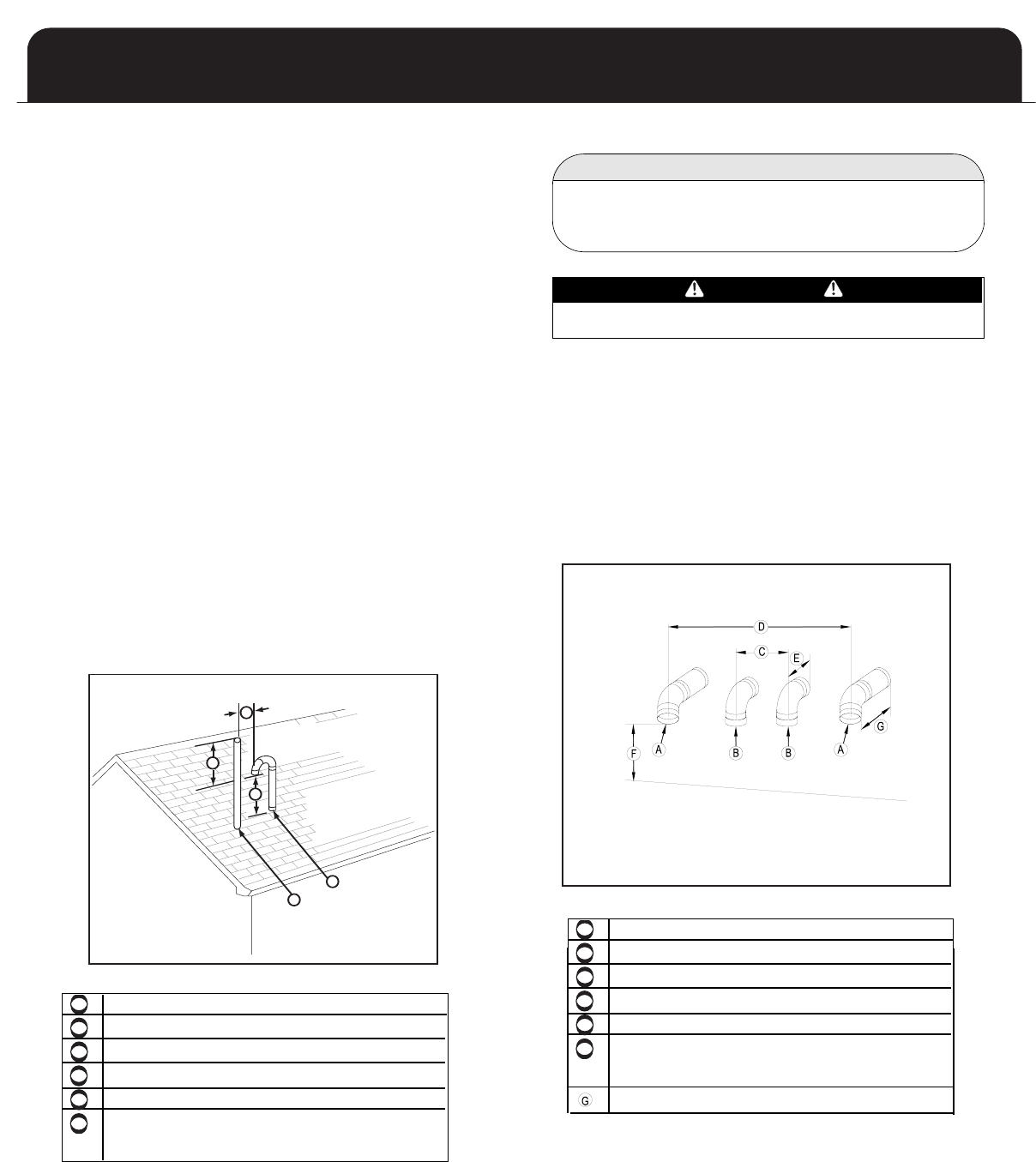
Vertical Combustion Air Termination
T
he combustion air termination is a pair of 2” medium or
l
ong sweep 90° elbows pointing downward to prevent rain
from entering the combustion air intake piping.
If 3” piping is used, it should be reduced to 2” within 18”
of the point where the pipe penetrates the roof. The ter-
mination inlet must be positioned within 3” of the com-
panion exhaust piping.
The combustion air inlet must be located a minimum of
12” above the anticipated snow level, and 12” below the
exhaust outlet.
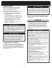
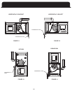
V
ertical Exhaust Vent Termination
The exhaust vent may terminate in a vertical venting
configuration through the roof.
No termination fitting is required if venting vertically
through a roof. The end of the exhaust pipe must be 12”
higher than the entrance of the combustion air intake
terminal.
The exhaust pipe extending through the roof must extend
a minimum of 18” above any obstruction within an 18”
horizontal distance.
VERTICAL TERMINATION OF
COMBUSTION AIR
AND EXHAUST VENT
A
B
C
TOP VIEW
INTERIOR
EXTERIOR
C
D
J
A
B
I
A
B
E
D
C
F
H
A
A
C
D
E
E
D
B
B
C
D
F
F
B
E
G
A
A
B
D
A
D
G
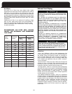
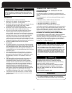
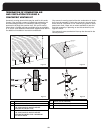
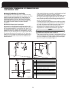
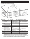
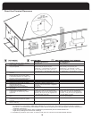
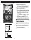
WARNING
COMMON VENTING IS PROHIBITED
If two of these furnaces are to be installed in close proximi-
ty, the combustion air intake and exhaust terminations may
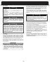
If more than two furnaces are being installed in close prox-
imity, each additional combustion air intake and exhaust
termination set must be installed a minimum of 4 feet
apart. This is an exception to the 10 foot requirement men-
tioned in the “Location” section on the previous page. If
using the concentric venting kits, two terminals may be
centered 12 inches apart.
When installing multiple furnaces in close proximity,
each requires dedicated combustion air and exhaust
venting.
IMPORTANT
MULTIPLE VENTING
21
Figure 10
be installed as shown in Figures 10.
8”