


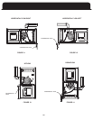
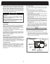
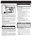
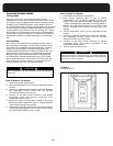

THERMOSTAT
COOLING
CONTACTOR
FAN
RELAY
HEATING RELAY
24V
115V
R
G
Y
W
Y
G
W
ISOLATION RELAY
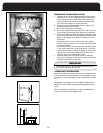
THERMOSTAT LOCATION
The thermostat should be located approximately 5 feet above
the floor, on an inside wall where there is good natural air
circulation, and where the thermostat will be exposed to
average room temperatures. Avoid locations where the
thermostat will be exposed to cold drafts, heat from nearby
lamps or appliances, exposure to sunlight, heat from inside
wall stacks, etc.
THERMOSTAT HEAT ANTICIPATOR SETTING: 0.45 AMP (White-
accessories such as electronic air cleaners and power
humidifiers.
ELECTRICAL WIRING AND COMPONENTS MUST BE PROTECTED
FROM MOISTURE, INCLUDING WATER AND CONDENSATE.
DEHUMIDIFICATION OPTION
The controller has a dehumidification option. When high
humidity is sensed (requires a 24 volt Humidistat that opens on
high humidity) the air flow is reduced to increase condensing.
To activate, the jumper labeled “DEHUM” must be moved to
the “yes” position.
AIRFLOW
WARNING
Make adjustments to the controller with the electrical
power off.
W
ARNING
ALL CONTROLLER JUMPER CHANGES MUST BE MADE
WITH POWER DISCONNECTED TO THE FURNACE.
The ECM TM blower is preprogrammed from the factory to
hold constant flow. (Replacement motors must have the
correct part number and can only be ordered from the furnace
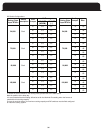
size A/C tonnage as well as an adjustment in flow. Changing
the Heating Tap changes the Temperature Rise in about 5 F
If the Adjust Tap is used for cooling then the heating speed
should be adjusted to counter the ef
fects of the adjustment
tap. Rule of thumb: The Heating Tap will be the same as the
START UP PROCEDURES
This furnace is equipped with a hot surface ignition (HSI)
device. Each time that the room thermostat calls for heat,
the HSI lights the main burners directly. See the lighting
instructions on the furnace.
To Start The Furnace:
1. Remove the burner compartment access door.
2. Shut off the electrical power to the furnace and set the
room thermostat to its lowest setting.
3. Ensure that the ignition system control switch on the
gas valve is in the “ON” position.
4.
Replace the burner compartment access door
.
5. Restore electrical power to the furnace.
6. Set the room thermostat to a point above room
temperature to light the furnace.
7. After the burners are lit, set the room thermostat to the
desired temperature.
To Shut Down The Furnace:
1. Set the room thermostat to its lowest setting.
2. Remove the burner compartment access door.
3.
The ignition system control switch on the gas valve may
be switched to the “OFF” position.
4. The furnace appliance shutoff valve may be closed if
desired.
SHOULD OVER HEATING OCCUR, OR THE GAS BURNERS
FAIL TO SHUT OFF, CLOSE THE MANUAL GAS VALVE FOR
POWER TO THE FURNACE. FAILURE TO DO SO CAN
CAUSE AN EXPLOSION OR FIRE RESULTING IN PROPERTY
DAMAGE, PERSONAL INJURY OR LOSS OF LIFE.
WARNINGi
THE FURNACE BEFORE SHUTTING OFF THE ELECTRICAL
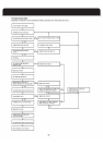
Sequence of Operation
1. Room temperature drops causing the room thermostat
heating W1 contacts to close.
2. The inducer blower is energized at high speed and the
control waits for the low pressure switch contacts to
close.
3. Once the low pressure switch contacts close, a 15-
second pre-purge is initiated. Then the inducer
powered.
heats up; 10 seconds on a first try, maximum 14 seconds
on a subsequent retry.
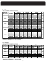
and cooling speed. Heating Tap A is factory set for heating speed.
increments. The Taps are in a row of jumper labeled “COOL”,
“HEAT” and “ADJUST”.
“ADJUST” Tap.
33
Rodgers) See page 39 for information on connecting optional
Table on page 36 shows the recommended taps for heating
manufacturer.) Changing the Taps allow adjustment for various
changes to low speed and the 120VAC ignitor is
4. After the prepurge period, the hot surface ignitor