


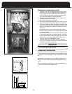
SETTING THE MANIFOLD (Outlet) GAS PRESSURE
(F92-1003 36G Valve Pressure Check Kit)
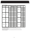
The manifold outlet pressure is specified on the rating
plate.
1. Shut off the gas upstream of valve and move valve
switch to OFF.
2
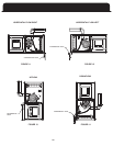
. Using the 3/32 inch hex wrench that is included in the
valve pressure check kit, rotate outlet pressure tap
screw one revolution counter-clockwise.
3
. Attach the 5/16 inch hose that is included in the valve
pre check kit to the outlet pressure boss of the valve.
Hose should overlap boss 3/8 inch.
4. Connect 5/16 inch side of connector that is included in
the valve pressure check kit to the hose on outlet boss.
Connect 1/4 inch side of connector to manometer hose.
5. Turn on gas supply to valve and move valve switch to
the ON position.
6. Turn on furnace. For the two stage valve the low rate
must be adjusted first and then the high rate. This can
be done by wiring the Thermostat so that only low fire
runs. Turn off the 1-stage T-stat mode on the control
board if set!
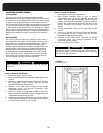
Remove regulator cover screw from the high or low
screw clockwise to increase pressure, or counterclock
Natural Gas: Low outlet pressure is limited to 1 to 4”
W.C. range and high outlet pressure 2 to 5” W C range.
The valve cannot be adjusted outside this range and
the high outlet pressure setting must always be set at
least 1” above the low outlet pressure setting.
LP Gas: Low outlet pressure is limited to 6 to 10” W.C.
range and high outlet pressure in the 8 to 12” W.C.
range. The valve cannot be adjusted outside this range
and the high outlet pressure setting must always be set
at least 2” above the low outlet pressure setting.
7. Using a leak detection solution check for leaks at hose
connections.
12. Turn outlet pressure tap screw clockwise to seal the
pressure point using the supplied hex wrench. Tighten
to 13 in-lbs. minimum. Return all pressure regulator
caps.
13. Turn on gas supply to valve and move valve switch to
the ON position.
14. Turn on furnace following manufacturer instructions.
15. Using leak detection solution check for leaks at outlet
p
ressure tap. Shut off gas and fix all leaks immediately
before proceeding.
If problems were encountered with obtaining enough
pressure on the manifold, first examine the gas piping
s
ystem to ensure that it is correctly sized. Pipe sizing is
specified in ANSI Z223.1/ NFPA 54 in the U.S., or the B148
Natural Gas and Propane Installation Code in Canada.
SETTING THE SUPPLY GAS PRESSURE
(F92-1003 36G Valve Pressure Check Kit)
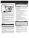
1. Back inlet pressure test screw (inlet/outlet pressure
boss) out one turn (counterclockwise, not more than
one turn) with a 3/32 inch Allen wrench.
2. Attach a hose and manometer to the inlet pressure boss
of the valve. The manometer should be capable of
reading 0 -15 inches water column.
3. Turn on the gas supply and electrical power to the
furnace.
appliances on the same gas piping system.
5. Note the gas inlet pressure. It should be: Natural Gas: 5
6. If working on a natural gas system, contact the gas
utility. They may insist on any service regulator
adjustments being made by their own staff.
7. Adjustments are made in a similar fashion as the gas
valve regulator. Turn the adjustment screw clockwise to
increase manifold pressure, or counter clockwise to
reduce manifold pressure. When the correct pressure
has been established, securely replace the service
regulator protective screw cap.
8. Shut off the gas at the manual valve and remove
manometer hose from inlet pressure boss.
DANGER
A TRAINED, QUALIFIED TECHNICIAN MUST DO ALL
REGULA
TOR ADJUSTMENTS. IMPROPER MODIFICATIONS
OR ADJUSTMENTS CAN RESULT IN FIRE OR EXPLOSION
CAUSING PROPERTY DAMAGE, SEVERE PERSONAL INJURY
OR LOSS OF LIFE.
DANGER
SHUT OFF GAS AND FIX LEAKS IMMEDIA
TELY BEFORE
PROCEEDING.
8. Read manometer. This reading is the system
outlet/supply pressure.
9. Follow manufacturer’s instructions to adjust
outlet/supply pressure, if necessary.
10.
Shut-off gas supply upstream of valve and move the
valve switch to the OFF position.
11. Remove manometer and hose from outlet boss.
In some circumstances, high inlet pressure can be remedied
with the use of an inline appliance regulator
. If an inline
appliance regulator is used, ensure that it has the capacity to
adequately handle the gas volume required by the furnace
and any other appliances receiving gas from the header
serving the furnace.
4. Start the furnace, and any other gas burning
outlet pressure regulator adjust tower and turn
as specified on the furnace rating label.
wise decrease pressure. Always adjust regulator
31
to 10.5 inches water column L.P. Gas: 11 to 13 inches
water column.