


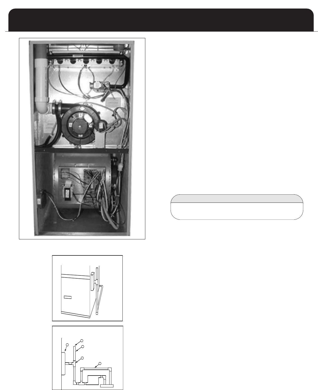
D
E
A
B
C
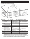
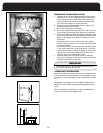
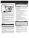
CONDENSATE NEUTRALIZERS
Some local codes may require the use of a condensate neu-
tralizer. If the furnace condensate is to be routed to a sep-
tic system, it may be advisable to use a condensate neutral-
izer.
Condensate neutralizers such as the Ward Industries 90+
Neutralizer are available through heating supply whole-
salers.
When condensate neutralizers are used, it is advisable to
install it with an overflow bypass tube.
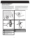
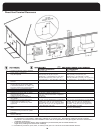
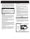
CONDENSATE DRAIN INSTALLATION
1. Identify which side the condensate drain trap will be
i
nstalled on the unit. Condensate trap may be mount-
ed on either the left or right side of the unit, when
looking at the front. Some installation positions will
only allow one option to mount the drain.
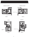
2
. Using the appropriate template (left vs. right), mark
the mounting and drain holes.
3
. Drill holes and de burr, if necessary
4. Secure the condensate drain trap to the side of the fur-
n
ace using the mounting holes that were just drilled
5. Install one rubber grommet (provided) into each of the
drain holes and then insert the 90 degree (black) drain
tubes so that they extend down into the top of the
drain trap.
Inside the top front cover, connect the drain tubing
from the flue connector to one of the drain pipes that
were just installed.
Do the same for the second drain pipe located located
in the lower right of the inner front panel. 1/2 ID tub-
ing should be used. It may be necessary to secure the
tubing with a hose clamp depending on the fit. Be
cautious not to over tighten the clamp.
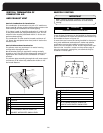
7. Pipe the remainder of the drain to the condensate
pump using PVC pipe. A 3/4” PVC coupling will fit over
the drain connection on the trap.
The condensate drain trap assembly should be full of
water before starting the furnace.
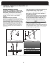
IMPORTANT
27
B - Open to
Atmosphere
Assembly)
E - Overflow
Bypass Tube
Higher than Trap
D - Tee(1/2" PVC)
PVC)(Minimum 1"
C - Standpipe (1/2"
A - Condensate
Trap Assembly