


CONDENSATE DRAINS
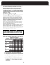
The furnace will condense as much as a half pound of
water per hour (approximately 2 imperial quarts, 2
1
/
2
U.S.
quarts or 2
1
/
4
liters). It is necessary to make provisions for
draining the condensate away.
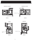
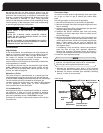
The furnace is supplied with a drain trap assembly. See
The drain coupling on the inducer will work better if the
drain holes are pointed down about 15 degrees. The drain
hose supplied with the furnace is long enough to reach
either side panel; however, it must be cut near the blower
division panel and fitted with the elbows and clamps pro-
vided. This is to prevent kinking in the drain lines.
CAUTION
The two inlets to the drain trap are for vent pipe and
condensate collection. The vent pipe inlet is smaller
than the condensate collection inlet. Ensure that the
drain hoses are properly connected.
CAUTION
Ensure that drain hoses do not create traps prior to the
condensate trap assembly. A secondary trap will cause
intermittent operation due to the pressure switches
opening.
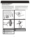
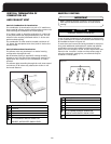
DRAIN HOSE INST
ALLATION
1. Select a drain trap location suitable for the orientation
of the furnace and remove the corresponding knock-
2. Affix the drain trap assembly to the exterior of the side
panel when the furnace is upflow or downflow using
two screws provided. For horizontal positions the
installer will need to use the mounting bracket sup-
plied and secure the bracket to the top panel. Remove
two top panel screws and fasten bracket to top panel
with removed screws. Secure trap assembly using
screws provided to the mounting bracket.
2. Slide a hose clamp over the end of each hose.
3. Slide each hose over the appropriate inlet.
4. Slide each hose clamp to approximately 1/8” from the
end of the hose.
5. Fasten each drain hose to its inlet by tightening the
hose clamps.
6. Cut each drain hose near the blower division panel, at
the point where kinking is able to occur.
7. Slide a hose clamp over the ends of the hose connect
-
ing to the vent drain and condensate drain.
8. Insert an end of the plastic elbow (supplied) into each
hose.
9.
Cut hose lengths from the remaining lengths of hose
to fit between elbows and the drain trap inlets of both
the vent drain and the condensate drain.
10. Slide a hose clamp over the ends of the hoses and
secure to their appropriate connection.
Slide each hose clamp to approximately 1/8” to 1/4”
from the end of the hose then tighten.
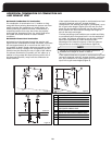
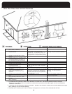
DRAIN PIPING
C
ondensate from the outlet of the drain trap assembly
must be conveyed to a floor drain, sump pit, or, if these are
unavailable, to a condensate pump. If using a condensate
pump, be sure that it is approved for use for furnace
c
ondensate.
CAUTION
Do not drain the condensate outdoors. Do not run the
condensate line through areas where freezing might
occur. Freezing of condensate can result in erratic fur-
nace operation and in property damage.
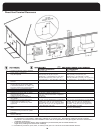
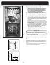
The condensate drainage configuration requires a vent. It
takes less than a one inch rise anywhere along the horizon-
tal route of the drain tube to create a vapor lock, which
will prevent condensate from draining away freely, and
result in erratic furnace operation.
If an air conditioning evaporator coil drain is to share
the furnace drain line, it should be connected with a
tee fitting down-stream from the trap. Do not connect
the evaporator coil condensate drain upstream of the
furnace drain trap assembly
.
IMPORTANT
DRAINAGE WITH VENT.
(NEXT PAGE)
FIGURES 11-14 : CONDENSATE TRAP / CONDENSATE
25
outs. See page 26, figures 11-14.
page 26, Figures 11-14 for possible locations of the drain trap.