


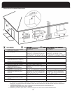
DANGER
THE FURNACE CABINET MUST HAVE AN
UNINTERRUPTED GROUND.
A GROUND WIRE IS PROVIDED IN THE ELECTRICAL
JUNCTION BOX.
DO NOT USE GAS PIPING AS A GROUND.
FAILING TO GROUND THE FURNACE PROPERLY CAN
RESULT IN ELECTRIC SHOCK RESULTING IN PERSONAL
INJURY OR DEATH.
WARNING
THIS FURNACE IS EQUIPPED WITH A BLOWER DOOR
SAFETY SWITCH. DO NOT DISABLE THIS SWITCH.
FAILURE TO FOLLOW THIS WARNING CAN RESULT IN
ELECTRICAL SHOCK, PERSONAL INJURY, OR LOSS OF LIFE.
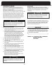
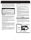
If the junction box must be moved to the right hand side:
1. Unfasten the junction box from the left hand side.
2
. Remove the right side panel knockout.
3. Remove the junction box cover hook screw and reinstall
i
t on the opposite side of the box.
4. Fasten the junction box to the right hand panel.
Low Voltage Wiring
The low voltage terminals are located on the control board
The furnace is prewired for air conditioning. Insert the
thermostat and air conditioner contactor low voltage
wiring through the bushing provided in the side panel.
Route the control wiring through the blower compartment
to the 24 volt terminal screws.
Thermostat
The room thermostat must be compatible with the
integrated control in the furnace. Electromechanical
thermostats should be rated 30 V / 1.5 amps.
Most electronic or microprocessor based thermostats except
those with "current robbing" circuits should work
satisfactorily
. Consult the instructions of the thermostat
manufacturer for technical and installation details.
Most compatibility problems can be overcome by the use of
an isolation relay
. The isolation relay should be SPST with a
24-volt coil. The switch ratings should be a minimum of 0.5
The thermostat and control wiring should be a minimum of
18 AWG copper. Excessive lengths of wire may result in
enough voltage drop to impair the proper functioning of
the furnace. For thermostat wires in excess of 25 feet, use
16 A
WG; 50 feet, use 14 AWG.
CAUTION
ELECTRICAL WIRING AND COMPONENTS MUST BE
PROTECTED FROM MOISTURE, INCLUDING WATER AND
CONDENSATE.
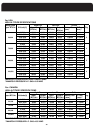
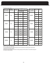
ELECTRICAL SPECIFICATIONS
Before proceeding with the electrical connections, ensure
that the available electrical supply is compatible with the
voltage, frequency, and phase listed on the appliance rating
p
late.
All furnaces are rated 120 VAC, 60 Hz, 1 phase. The
amperage rating is indicated on the furnace rating plate.
Each furnace requires a dedicated overcurrent device either
a circuit breaker or a Type D, time delay fuse. It is
permissible to connect furnace accessories such as
humidifier transformers, condensate pumps and electronic
air cleaners. If adding accessory equipment to the furnace
circuit, ensure that the combined amperages listed on the
appliance rating plates do not exceed the rating of the over
current device.
DANGER
SHUT OFF ELECTRICAL POWER AT THE FUSE BOX OR
SERVICE PANEL BEFORE MAKING ANY ELECTRICAL
CONNECTIONS. FAILURE TO DO SO CAN CAUSE
ELECTRICAL SHOCK RESULTING IN PERSONAL INJURY OR
LOSS OF LIFE.
In the United States, all electrical work must be in
accordance with the latest edition of the National Electrical
Code, ANSI / NFPA 70, in Canada, all electrical work must be
in accordance with the latest edition of CSA-C22.1, Canadian
Electrical Code Part 1, and any applicable local code.
Although a suitably located circuit breaker may serve as a
service switch, a separate service switch is recommended.
A separate service switch is necessary if the circuit breaker is
in a location where accessing it would require getting close
to the furnace, or if the furnace is located between the main
electrical panel and the entry to the furnace room. The
furnace switch (service switch) should be clearly labeled and
installed in a location where it is not likely to be mistaken as
being a light switch or similar control.
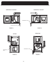
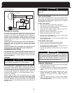
Furnace Connection
120V
: The furnace is shipped fully wired except for the
connections to the house wiring. The furnace power
connections are made in a junction box inside the blower
compartment. The junction box is factory installed on the
left hand side; however, it may be moved to the right hand
side. The junction box contains a BLACK wire to be
connected with L1 (hot), a WHITE wire to be connected with
L2, the Neutral, and a GREEN wire to be connected to the
ground.
USE COPPER CONDUCTORS ONLY
IMPORTANT
L1 (hot) and L2 (Neutral) polarity must be observed
when making field connections to the furnace. The
ignition control may not sense flame if L1 and L2 are
reversed. The ground is also essential.
IMPORTANT
The furnace shall be installed so the electrical
components are protected from water.
IMPORTANT
amps; see figure on next page.
32
mounted to the blower assembly; see Figure 15 on page 37.