


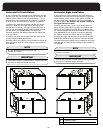
Guidelines
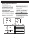
• Venting may be vertical or horizontal.
•
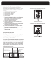
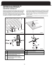
• Horizontal piping must slope back towards the furnace
at a minimum rate of 1/4” to the foot, so that
• Horizontal runs must be supported at least every 3
feet. Horizontal sections must not dip or sag
• All vent runs through unconditioned space where
freezing might occur should be insulated with 1”
thick, medium density, foil-faced Fiberglass insulation.
An equivalent “arm-aflex” or “rub-a-tex” may also be
used as long as there is no heat tape applied to the
vent pipe. For horizontal runs where water may
collect, wrap the vent pipe with self regulating 3 or 5
watt heat tape. The heat tape must be CSA, UL, or ULC
listed and installed per the manufacturer’s instructions.
• DO NOT COMMON VENT WITH ANY OTHER
APPLIANCE.
• If venting vertically, do not vent up a chimney serving
another appliance or install in a chase with a metal or
high temperature plastic pipe from another gas or fuel
burning appliance unless the required clearances to
combustibles can be maintained between the PVC pipe
and other pipes.
• All exhaust piping must be installed in accordance
with CAN/CGA-B149.in Canada; the latest edition of
National Fuel Gas Code, NFPA 54 / ANSI Z223.1 in the
United States, as well as in accordance with local
codes.
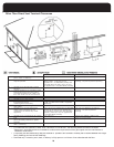
• Take the building orientation and the presence of
other buildings or other nearby structures into
consideration when planning the venting system
location. Certain external structures could create air
turbulence around the vent termination leading to
downdrafts and similar venting problems. In windy
and hill locations, roof venting may improve
operations. Maximum venting length is based on 30
mph winds, areas where higher gusts are dominant it
is suggest to shorten the horizontal vent length,
increase the diameter of the vent, or vent vertically.
•
The exhaust vent and combustion air intake shall be
installed so that both are located in the same wind
pressure zone.
CAUTION
FAILURE TO FOLLOW ALL VENTING GUIDELINES MAY
RESULT IN ERRATIC FURNACE OPERATION, FREEZE-UP
OF THE VENTILATION AIR PIPING, OR SOOTING OF THE
FURNACE.
DANGER
SOLVENT CEMENTS AND PRIMERS ARE HIGHLY FLAM-
MABLE. PROVIDE ADEQUATE VENTILATION AND DO
NOT ASSEMBLE NEAR HEAT SOURCE OR OPEN FLAME.
DO NOT SMOKE. AVOID SKIN OR EYE CONTACT.
OBSERVE ALL CAUTIONS AND WARNINGS PRINTED ON
MATERIAL CONTAINERS. FAILURE TO FOLLOW THESE
GUIDELINES MAY RESULT IN FIRE, EXPLOSION OR AS-
PHYXIATION CAUSING PERSONAL INJURY OR LOSS OF
LIFE.
JOINING PIPE AND FITTINGS
Acceptable Materials for Combustion Air and
Exhaust Vent Pipe
The furnace products of combustion include both flue
gases and condensate. All venting and drain materials are
p
lastic.
The combustion air and vent piping and fittings may be
comprised of:
• Schedule 40 PVC, ASTM D1785 or CSA B137.3
• PVC-DWV, ASTM D2665 or CSA B181.2
• ABS-DWV, ASTM D2661 or CSA B181.1
• Schedule 40 CPVC, ASTM F441 or CSA B137.6
In Canada, construct all combustion-air and vent pipes for
this unit of CSA or ULC S636 listed schedule-40 PVC, PVC-
DWV or ABS-DWV pipe and pipe cement. SDR pipe is not
approved in Canada. In addition, the first three feet of the
exhaust must be accessible for visual inspection.
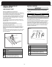
Procedure for Cementing Joints (ASTM D2855):
It is preferable to use a single type of plastic throughout
the venting and combustion air piping; however, if
dissimilar piping or fitting materials are used, they must be
joined with an appropriate transition cement. Dissimilar
pipe segments may be joined together by mechanical
means (i.e., 2” rubber coupling).
WARNING
All pipe, fittings, solvent cement, primers and
procedures must conform to American National
Standards Institute and American Society for Testing
Materials (ANSI / ASTM) standards.
PIPE AND FITTINGS: ASTM D1785, D2466 and D2564
PVC PRIMER AND SOLVENT CEMENT: ASTM D2564
ABS PIPE AND FITTINGS: Use ABS Primer and Solvent
Cement D2235
CPVC SOL
VENT CEMENT
: F493
For proper installation, DO NOT thin or use solvent
cement that has become curdled, lumpy or thickened.
IMPORTANT
16
condensate drains towards the furnace.
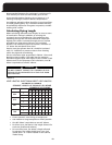
Minimum vent length - 25 total equivalent feet.
(See page 18, Table 4 - Venting Table)