


DUCTWORK
Proper airflow is required for the correct operation of this
furnace. Insufficient airflow may cause erratic operation,
c
ould cause the furnace to cycle on the high temperature
limit, and may damage the heat exchanger. Excessive
airflow may result in an excessively noisy duct system and
may result in undesirable consequences such as creating
uncomfortable drafts and causing drapes or curtains to
b
low around.
If air conditioning is to be used with the furnace, the duct
system must be capable of delivering the correct amount of
a
irflow for each system.
The ductwork should be sized and constructed in
accordance with accepted industry standards. Duct sizing
and construction information may be obtained from:
• A.C.C.A. (Air Conditioning Contractors of America)
• A.S.H.R.A.E. (American Society of Heating,
Refrigeration and Air Conditioning Engineers)
• H.R.A.I. (Heating, Refrigerating and Air Conditioning
Institute (Canada)
• S.M.A.C.N.A. (Sheet Metal and Air Conditioning
Contractors’ National Association (United States)
All of the above professional organizations have duct sizing
manuals available.
The total static pressure drop of the air distribution system
should not exceed 0.5 inches water column.
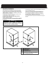
Ductwork Steps:
1. Position the furnace to minimize ductwork length and
fittings.
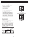
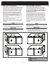
2. Cut open a return air inlet. The choices are:
a) either side
b) furnace bottom
c) any combination, i.e. two sides or a side and the
bottom.
In all cases, cut the inlet air opening the full width of
CAUTION
DO NOT USE THE REAR PANEL AS A RETURN AIR INLET.
THERE IS INSUFFICIENT AREA TO PERMIT ADEQUATE
AIRFLOW.
3. Install the filter rack(s) (field supplied).
4. Connect the return air duct or fitting to the furnace. The
connection should be as air tight as possible to prevent
entraining combustion gases from an adjacent fuel
burning appliance, or entraining combustion air for this
furnace .
5. Ensure that there is adequate space and accessibility for
the air filter
.
6. If an air conditioning evaporator coil is required,
position it on the top of the furnace. Ensure that no air
can bypass the evaporator coil.
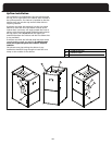
7. Connect the supply air plenum to the supply air outlet.
Flexible duct connectors are an effective device to
prevent the telegraphing of mechanical noise from the
furnace to other parts of the home via the ductwork. If
using flexible connectors, ensure that the adjoining
duct is independently supported.
Adequate provisions for combustion and ventilation air
must be in accordance with ANSI Z223.1 (NFP
A 54), section
5.3 "Air for Combustion and Ventilation" in the United
States, and CAN/CGA B149 in Canada. Check with local
authorities for any additional building codes, bylaws or
regulations.
WARNING
DO NOT, UNDER ANY CIRCUMSTANCES, CONNECT
RETURN OR SUPPLY AIR DUCTWORK TO OR FROM ANY
O
THER HEAT-PRODUCING DEVICE SUCH AS A FIREPLACE
INSERT, STOVE, ETC. DOING SO MAY RESULT IN FIRE,
CARBON MONOXIDE POISONING, EXPLOSION,
PERSONAL INJURY, LOSS OF LIFE, OR PROPERTY
D
AMAGE.
Some high efficiency filters have a greater than nor-
mal resistance to airflow. This can adversely affect fur-
nace operation. Pressure check the static differential
from before the filter to the supply.
IMPORTANT
When two return air inlets are used, both must be
equipped with filters.
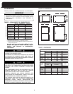
NOTE
When calculating an air filter size use the free air not
the advertised size.
NOTE
UNITS FOR 4 AND 5 TON CF AIR CONDITIONING MUST
HAVE DUAL RETURN AIR INLETS FOR OPTIMAL
AIRFLOW AND AIR FIL
TRA
TION. IF NOT SPECIFICALLY
STATED BY THE FILTER MANUFACTURER, FOR
EFFECTIVE AIR FILTRATION, ASSUME A MAXIMUM
VELOCITY OF 300 FPM FOR DISPOSABLE TYPE FIL
TERS,
OR 600 FPM FOR PERMANENT TYPE FILTERS.
NOTE
Guide:
Filter free area (in
2
) = 144 x (CFM / desired velocity (fpm))
7