


T
C
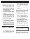
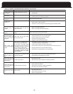
8
S1
O
D
M
70-4 Cool
Cool
1
b
1150
1On
1000
3
a
A
2
Off
810
1
Off
650
2.5 B
2
On
1
On
2C
2
On
1
On
1.5 D
A
B
B
C
D
A
B
C
C
D
1550 4
1350
1150
3.5
1000
810
3
a
2.5
2
S3
2
1
2
1
2
1
2
1
2
1
2
On
Off
Off
On
Off
Off
On
On
On
On
On
S385-4
All Delay
5
5
Off
6
On
5
On
6
On
5
On
T
No
delay
No
delay
1
30
30
Off
0
On
C
B
D
S4
6On
S
180
30
Off
On
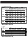
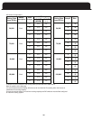
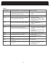
Model
Desc. Bank Switch Pos.
CFM AC
Ton
Tap
1 Off
1350 3.5
b
A
2 Off
1150
1On
3
a
A
2
Off
810
1
Off
2
On
1
On
On
A
B
B
C
S3
Switch
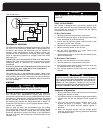
ADJUSTING BLOWER SPEEDS
Cooling Mode
The unit is factory set to provide the highest airflow.
A
djustments can be made to match the furnace with a small-
er cooling coil by changing the DIP switch or jumper settings,
located on the integrated ignition control board. Refer to
Heating Mode
The unit is set from the factory to operate at the center of
the temperature rise range. For this model furnace, the air
airflow can be increased or decreased by changing the
heating mode DIP switches or jumpers, located on the inte-
grated ignition control board, to the Nominal-plus/minus
settings. Please note that Nominal-plus will decrease the
air temperature rise and the Nominal-minus will increase
the air temperature rise. At the end of a call for heat, the
main blower has a fixed off delay at a reduced airflow to
remove residual heat from the heat exchanger.
the Cooling DIP switch or jumper settings table for instructions
on how to set the switches. Please note that if the furnace is
to be matched to the lowest airflow for cooling, the "Adjust"
DIP switches or jumper setting must be set to the decreased
setting. When using this setting, it is recommended that the
Plus.
temperature rise is between 35 and 65 degrees F. Heating
Make adjustments to the controller with the electrical
power off.
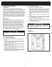
WARNING
front blower shroud from furnace.
How To Remove The Blower
1. Disconnect power from furnace.
2. Remove thermostat wiring from the integrated furnace
control.
3. Remove L1, Neutral and Ground connections between
the integrated furnace control and the Furnace
electrical connection junction box.
4. Remove 12 pin male molex connector from female
connection point, and ground connection from
integrated furnace control.
5. Unscrew 2 blower housing bolts located in the front
6. Slide blower assembly towards front of furnace. Blower
is mounted on rail system, and will slide forward about
10 inches before blower is clear of rails.
6. Turn on power to the furnace.
integrated furnace control.
connection point, and ground connection to the
5. Connect 12 pin male molex connector to female
electrical connection junction box.
the integrated furnace control and the furnace
4. Connect L1, Neutral and Ground connections between
control.
3. Connect thermostat wiring to the integrated furnace
tighten.
blower housing. Insert blower housing bolts and
blower rails. Insert blower shroud on the front of the
urnace ensuring blower assembly is correctly placed in
blower rails. Push blower assembly towards back of
compartment. Line up blower assembly to slide into
2. Keep blower assembly tight to top of blower
1. Place blower into blower compartment.
How To Install The Blower
Ensure that there is a drip bend in the connect wires to
the blower motor to prevent condensate from following
the wire into the connector.
WARNING
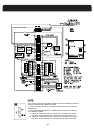
Bolts
BLOWER BOLTS
FIGURE 15
blower shroud as indicated in figure 15 (right). Remove
37
Heating DIP switches or jumper setting be set for Nominal-