


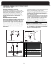
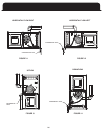
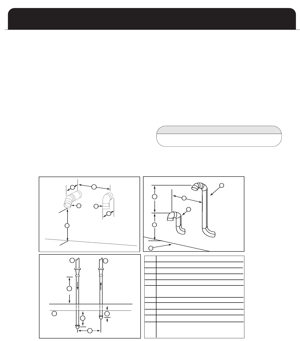
If the required clearance to grade or anticipated snow level
cannot be obtained with the “straight through”
c
onfiguration, the exhaust pipe may be “periscoped” up to
2
4” to gain extra height. (Figure 9) In this case, the flue
gases may be expelled horizontally. Use the same size pipe
as the interior run and count the fittings and length as
part of the total vent length.
If winter prevailing wind conditions are variable and likely
to occasionally blow flue gases back in on the combustion
air intake, the exhaust termination may be raised 18-24”
above the combustion air intake terminal to take
advantage of the natural buoyancy of the flue gases to
help prevent re-circulation of the exhaust. (Figure 9)
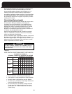
Length of pipe and elbows count toward maximum
allowable vent length as shown in Table 4.
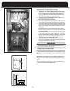
NOTE
H
orizontal Combustion Air Termination
The combustion air termination is a 2” medium or long
sweep 90° elbow pointing downward to prevent rain from
readily entering the combustion air intake piping. An
intake screening is optional; however, unless there is a
compelling reason to use one, the screen may actually
e
ncourage the formation of rime ice, which could cause
t
he intake to become blocked in certain weather
c
onditions.
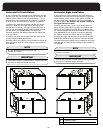
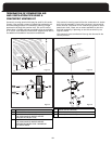
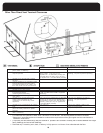
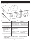
Horizontal Exhaust Vent Termination
Horizontal vents should pass through the exterior wall.
Figure 8 shows a standard horizontal vent detail. Terminate
the vent approximately 8” or more from the wall. If it is
not possible to obtain proper clearance to grade or antici-
pated snow level by a straight out configuration, the ter-
mination may be raised by the use of a pair of 90° elbows.
The exhaust termination is normally a 2” 45° elbow or a
medium or long sweep 90° elbow pointing within 45° of
the downward position, away from the combustion air
intake terminal.
HORIZONTAL TERMINATION OF COMBUSTION AIR
AND EXHAUST VENT
If the required clearance to grade or anticipated snow level
cannot be obtained with the “straight through” configura-
tion, the combustion air intake pipe may be “periscoped”
up to 24” to gain extra height (Figure 9)
TOP VIEW
INTERIOR
EXTERIOR
C
D
J
A
B
I
B
F
H
A
A
C
D
E
E
D
B
B
C
D
E
ROOF
OVERHANG
B
C
D
G
12”-18”
EXHAUST VENT
COMBUSTION AIR
8”
12”
2”
12” CLEARANCE ABOVE GRADE OR
ANTICIPATED SNOW LEVEL
12”- 18”
GRADE OR ANTICIPATED SNOW LEVEL
18” MAX
OUTSIDE WALL
A
B
C
D
E
F
G
H
I
J
20
Figure 7
Figure 8
Figure 9