


OV500 SERIES RACK OVEN - SERVICE PROCEDURES AND ADJUSTMENTS
IGNITION MODULE SELF
DIAGNOSTICS
Ignition module makes three attempts to light burner
before proceeding to lock-out mode.
1. Turn oven on and set controller to call for heat.
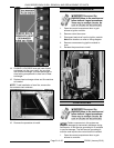
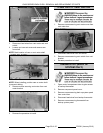
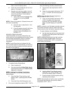
2. Access the ignition module by removing
component panel cover.
3. Check ignition module indicator LED for fault
codes as stated in following chart.
NOTE: LED will briefly illuminate during pre-purge.
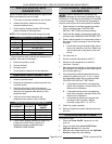
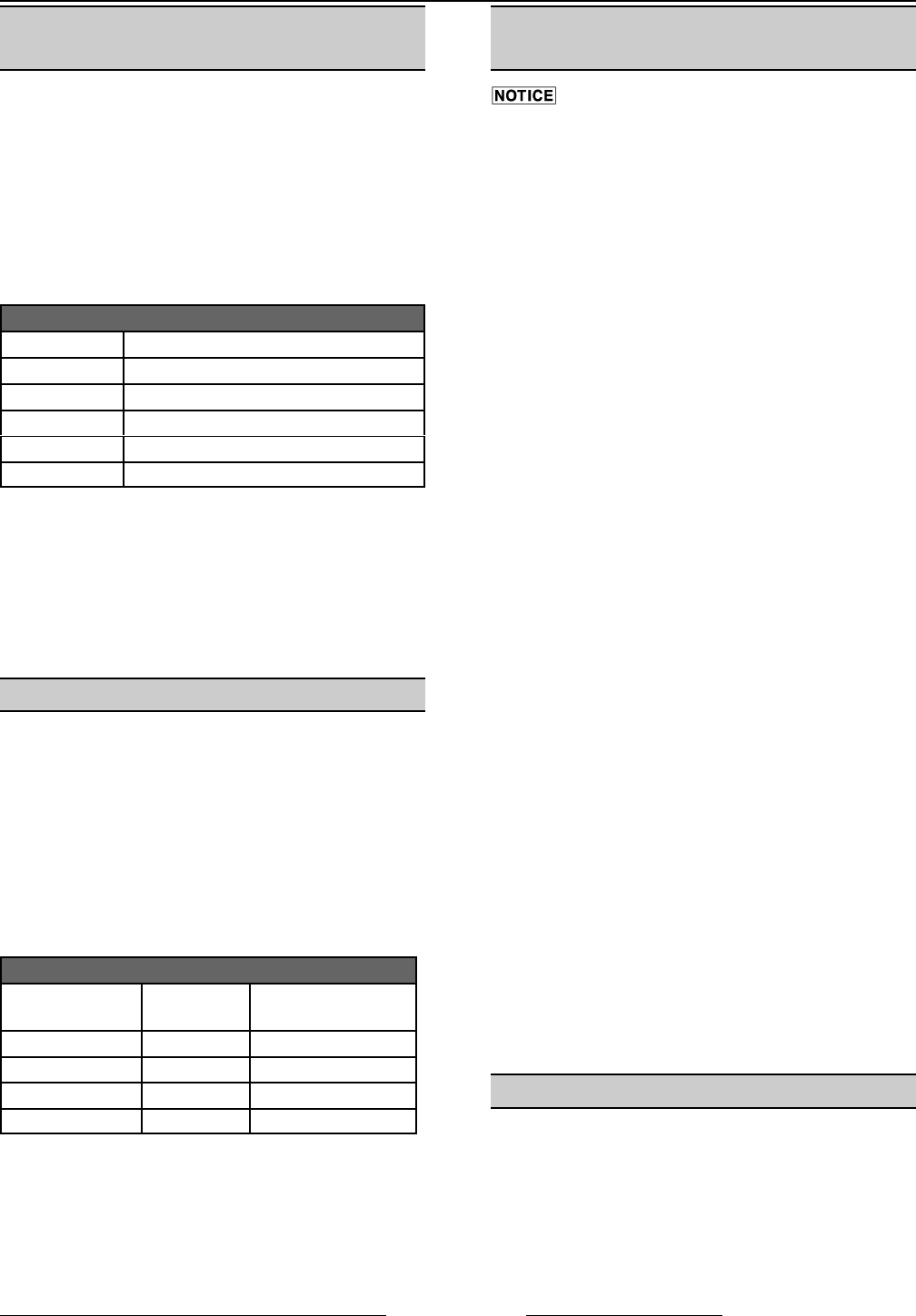
LED DIAGNOSTIC INDICATOR CODES
LED CODES
LED off No Fault
LED on Control Fault
'1' Flash Air Flow Fault
'2' Flash Flame No Call For Heat*
'3' Flash Ignition Lockout
* Flame continues after controller set temperature is
satisfied. (Gas valve sticks open.)
4. Disconnect power to oven.
5. Correct the fault.
6. Re-apply power.
7. Check ignition module for correct operation.
TEMPERATURE PROBE TEST
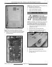
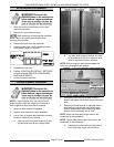
1. Access controller board.
2. Disconnect temperature probe lead wires from
controller board.
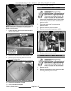
3. Set the multi meter to milli volt scale and
connect positive lead (red) to the (white) probe
lead wire and negative lead (black) to (red)
probe lead wire.
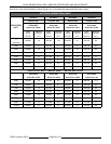
4. Verify the multi meter reading to the
temperature conversion chart as follows.
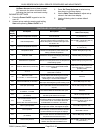
TEMPERATURE CONVERSION CHART
FAHRENHEIT CELSIUS
MILLIVOLT
RANGE
100 38 -1.8 to 1.2
200 93 1.5 to 4.3
300 149 4.5 to 7.3
400 204 7.5 to 10.6
5. If multi meter reading indicates an open or is
outside the millivolt range, replace the
temperature probe as outlined under
TEMPERATURE PROBE.
CONTROLLER TEMPERATURE
CALIBRATION
Certain components in this system are
subject to damage by electrostatic discharge during
field repairs. A field service grounding kit is available
to prevent damage. The field service grounding kit
must be used anytime the control board is handled.
1. Check setting of controller temperature offset
(P4) as outlined under CONTROLLER
DEFAULT SETTINGS and record setting.
2. Verify that the probe is functioning properly as
outlined under TEMPERATURE PROBE TEST.
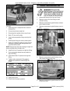
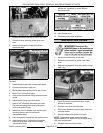
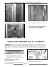
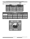
3. Place a thermocouple of a temperature tester in
the center of right incoming air slot of the bake
chamber.
A. Route thermocouple through hinge side of
door to the outside of the oven. Make sure
that the lead wire is kept clear of the rack
carrier.
4. Turn the oven on.
5. Set the controller temperature to 400EF.
6. Allow the oven temperature to stabilize
(minimum 3 cycles).
7. Note temperature reading on temperature tester
and controller at the exact time the heat light on
the controller goes out.
8. If the temperature difference between the two
readings is greater than ±2EF or ±1EC, adjust
the temperature offset (P4) as outlined under
CONTROLLER DEFAULT SETTINGS.
A. If temperature test shows a temperature
higher than controller, increase offset (P4)
the amount of difference.
B. If temperature test shows a temperature
lower than controller, decrease offset (P4)
the amount of difference.
C. If temperature difference is greater than
the range of the controller, replace
controller (range ±50EF. or ±10EC.).
9. Check for proper operation.
10. Remove temperature tester thermocouple from
the oven.
CONTROLLER SETTINGS
CLOCK SETTING
1. Press the Power On/Off keypad to turn the
oven on.
2. Press and hold either Auto On/Off Timer
Up/Down Arrows for 3 seconds.
3. After the colon stops flashing use the Up/Down
Arrows to adjust the clock setting.
F25361 (January 2010)
Page 29 of 60