


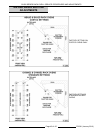
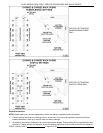
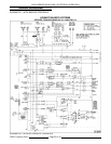
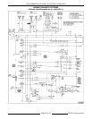

OV500 SERIES RACK OVEN - ELECTRICAL OPERATION
A. 24V transformer heating circuit / 24V
transformer door switch circuit / control
board / M3 / CR1 / Lights / MR1 / SV1 / M2
/ M4 / M5 / CR3 / CR2 back up control only
/ circuit breakers.
9. High limit, roll out switch and overloads
OL1and OL2 closed.
Pre - Heat Cycle
This condition exist as the operator prepares to
bake.
1. Oven at idle conditions.
2. Door closed (A2 lit).
3. Control power switch turned on.
A. Interior lights are illuminated.
B. Control energized - display is lit.
C. 5 second delay before call for heat.
4. End of 5 second delay.
A. CR1 de-energized (A5 not lit). Roof
mounted fan energized.
B. MR1 energized (A6 lit). Circulation motor
energized.
C. 24 VAC transformer energized.
5. Hood pressure switch closes.
A. 24 VAC to L1 and R of ignition control.
B. 24V to control (A4 lit).
6. Heat output from oven control (A8 lit).
A. Refer to burner sequence of operation for
burner details.
7. Oven will cycle at preheat temperature 375EF
default (191EC.) until operator changes the
conditions.
Bake Cycle
1. Oven at preheat temperature.
2. Operator sets conditions for bake cycle.
NOTE: If steam is part of the bake cycle, bake time
must also be entered and the steam cycle will always
be first.
3. Door is opened to load rack.
A. Control de-energizes outputs to ignition
module and circulation fan motor
contactor.
NOTE: If rack carrier is not in load position, the
control will position rack carrier in load position if
door is ajar.
4. Rack loaded onto carrier and close door.
A. DS1 N.C. contacts open (both sets).
B. DS1 N.O. contacts close (both sets).
C. CR4 coil energized.
1) CR3 de-energized.
2) Circuit path to lift motor completed thru
CR4 N.O.
D. Circulation motor energized.
E. Refer to burner sequence of operation.
5. Bake cycle started by pushing timer start
button.
NOTE: The door can be opened at anytime during
the bake cycle. If so, the rack will stop at home
position and lower. Circulation motor and burner will
not operate. Bake timer paused until door is closed.
A. Out put from control board to lift motor
(A11 lit).
1) Lift motor energized to lift rack.
2) After rack starts to lift LS2 N.O.
contacts open and N.C. contacts
close.
6. Rack reaches raised position.
A. LS1 N.C. contacts open.
1) Lift motor M5 de-energized.
B. LS1 N.O. contacts close.
1) Rotator motor M4 energized.
7. If steam is part of the bake cycle:
A. Water solenoid SV1 will be energized (A10
lit) for the required number of seconds.
NOTE: 30 seconds is the maximum number of
seconds that the control will energize SV1. The
steam time can be set to a maximum of 95 seconds.
B. Circulation motor and burner will not
operate. (A6 and A8 not lit)
8. Steam cycle ends:
A. Water solenoid SV1 de-energized .
B. Circulation motor and burner operate.
9. Remainder of bake cycle controlled by bake
timer.
10. Time expires and buzzer sounds.
11. Stop button pressed to silence buzzer.
NOTE: Rack remains in bake position and rotating
until door is opened.
12. Door opened to unload oven.
A. Control removes power from heat output
and circulation blower output.
1) Circulation motor and burner will not
operate while door is open.
B. DS1 N.C. contacts close (both sets).
C. DS1 N.O. contacts open (both sets).
F25361 (January 2010)
Page 49 of 60