


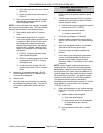
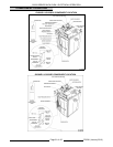
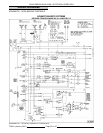
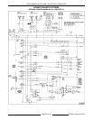
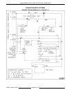

OV500 SERIES RACK OVEN - ELECTRICAL OPERATION
1) CR4 de-energized.
2) Door input removed from control board
(A2 not lit).
3) Circuit to rotator motor continues thru
CR4 N.C.
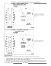
D. Rack continues to rotate until rack pointer
operates rack position switch #1 and #2.
(Rack centered in door).
NOTE: In some instances when the door is opened,
the rack may be centered in door. CR3 will energize.
Rack will stay centered in door and then lower.
E. Rack position switch #2 N.O. contacts
close.
F. Rack position switch #1 N.O. contacts
close. Input signals control board that rack
is centered in door for the first time since
stop button was pushed and door was
opened.CR3 energized thru rack position
switch #1 N.O. contacts. Latching circuit
keeps CR3 energized if rack would coast
past pointer.
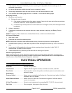
1) CR3 N.C. contacts open and rotator
motor M4 de-energized.
2) CR3 N.O. contacts close and lift motor
is energized thru LS2 N.C. contacts,
lowering the rack.
3) As the rack starts to lower LS1 N.O.
contacts open and LS1 N.C. contacts
close.
13. When rack is completely lowered, LS2 N.C.
contacts open and LS2 N.O. contacts close.
Lift motor is de-energized.
14. Remove rack.
15. Shut door and oven will continue to maintain
set temperature (preheat mode). The rack lift
will remain in load/unload position and not
rotate.
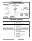
BURNER SEQUENCE OF
OPERATION
1. Power (24VAC) to ignition module L1 and R -
(A4 lit).
2. 24VAC output from control (A8 lit) to ignition
module terminal W and one side of the draft
inducer pressure switch.
A. Draft inducer motor energized from ignition
module terminal F2 (115VAC).
B. Inducer pressure switch closes.
1) Power to terminal PS.
3. Pre-Purge cycle begins (15 seconds).
4. Ignition module energizes hot surface ignitor
(24VAC) thru terminal S1 for 4 second heat up
time.
5. Gas valve energized thru MV1 two seconds
after start of hot surface ignitor cycle.
6. Top burner lights and flame spreads to all
burners.
7. Flame sensor rod is engulfed in flame and a
current is rectified between the flame and
ground thru the sensor. Ignition module
requires a steady 1.0 microamp to verify flame
presence.
NOTE: Ignition module makes three attempts to
achieve ignition. 30 seconds inter-purge between
each attempt. If after the three tries for ignition and
the burner has not lit, there will be an additional 15
seconds purge time. After which the ignition module
will enter a lock-out condition. The ignition module
utilizes a 3 blink code of the LED for this problem.
The ignition module will have to be reset by
removing power from the ignition module. To do this,
open the door or cycle the main circuit breaker
(110VAC) to the oven.
8. When set temperature is met, control removes
heat output to ignition module terminal W (A8
not lit).
A. Ignition module is de-energized.
1) Gas valve de-energized.
2) Draft inducer motor M3 de-energized
30 seconds after gas valve de-
energized.
B. Inducer pressure switch N.O. contacts
open.
F25361 (January 2010)
Page 50 of 60