


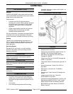
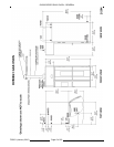
OV500 SERIES RACK OVEN - GENERAL
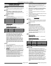
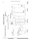
OV500E1 ELECTRIC OVEN
SPECIFICATIONS
â WATER:
1/2" NPT, 30-75 PSI cold water required, customer to
install in-line filter, shut off valve and line strainer.
Ï DRAIN:
6 1/4" (front) or 7" (rear) connection A.F.F. (See
notes). Route to air-gap drain. Do not slope drain
upwards. Plug the drain connection that is not in use.
Rear Drain: 1/2" NPTF
Front Drain: 1/2" NPTF
Ð POWER:
Two supplies required.
120/60/1 20 AMP dedicated circuit required and one
of the following voltage options.
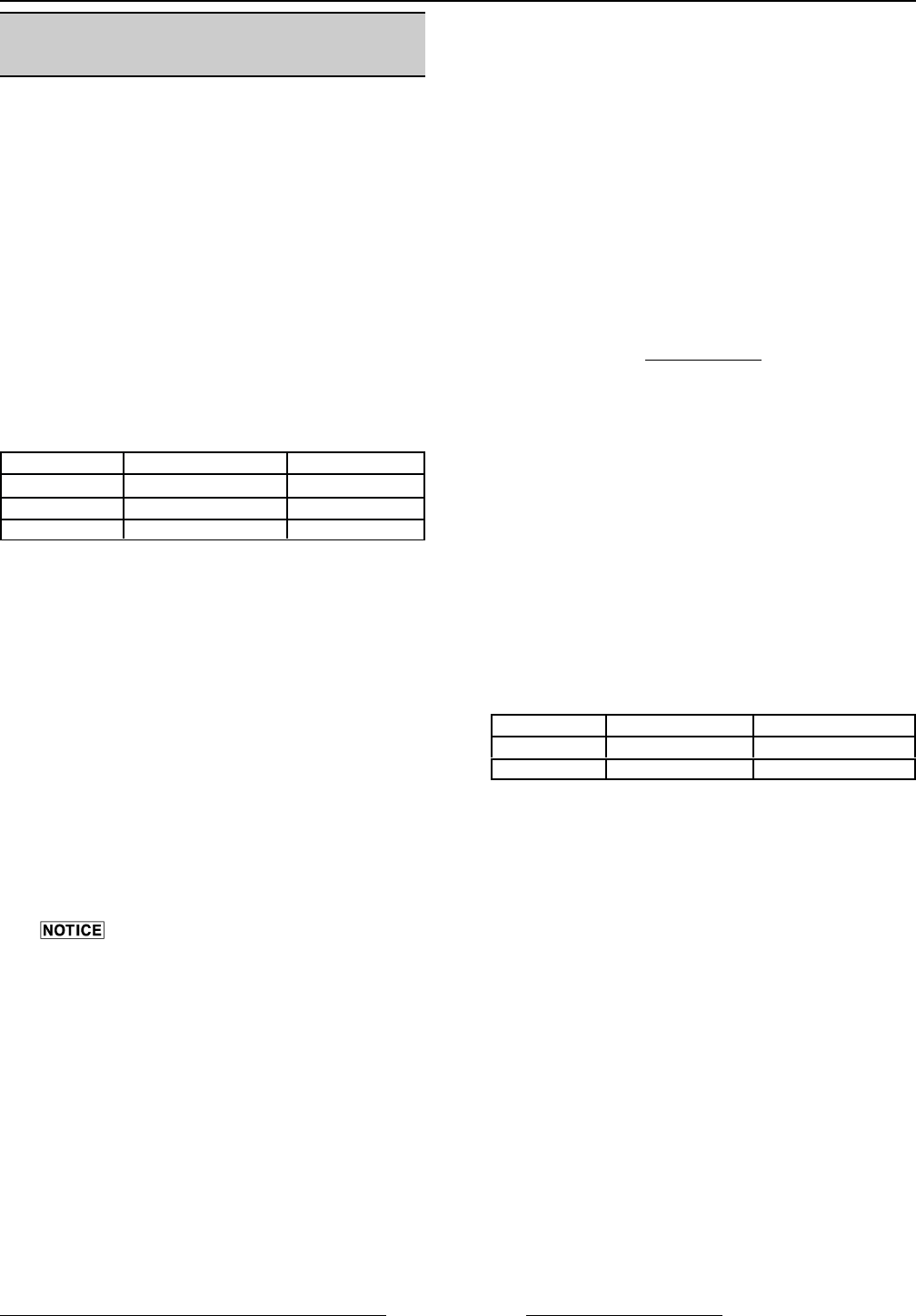
Heating Circuit: KW rating in following chart per
supply voltage.
Blower Motor: 1 1/2 H.P.
Voltage Full Load AMPS Heaters Rating
208/60/3 100 AMPS 34 KW
208 - 240/60/3 76 - 87 AMPS 26 - 34 KW
440 - 480/60/3 40 - 43 AMPS 29 - 34 KW
Ñ HOOD VENT:
8" DIA connection collar. Customer to supply duct
and ventilator fan per state and local codes. Oven
provided relay with max. 10 amp 1/2 H.P. @ 120V
output for fan operation. If larger, use oven relay to
control additional separately powered contactor /
relay for hood fan. Chamber vents are factory ducted
to this integral hood. 690 CFM required, 0.6" W.C.
static pressure drop through hood. Hood is UL710
Listed when grease filters are installed. Type B gas
vent can be used except when bake products are
grease laden.
NOTES:
1. A.F.F.: Above finished floor.
2. Customer responsible to finish and install all utilities
to and from oven.
3. All services must comply with all Federal, State and
Local codes.
4. To reduce the risk of fire, the appliance is
to be installed on non-combustible surface only, with
no combustible material within 18 inches above the
appliance. The appliance is to be mounted on floors
of non-combustible construction with non-
combustible flooring and surface finish and with no
combustible material against the underside, or on
non-combustible slabs or arches having no
combustible material against the underside. Such
construction shall in all cases extend not less than 12
inches beyond the equipment on all sides.
5. The floor must be of non-combustible material, and
must be level with surrounding area with a maximum
slope of 1/8" per foot up to 3/4" maximum in all
directions. Floor anchors require a minimum 1" thick
solid floor substrate.
6. Oven is UL/C-UL classified and CSA (AGA/CGA)
approved for 0" clearance on the side and rear walls.
Unit requires 1" to 4" clearance for rear drain
connection.
7. Top of oven requires a minimum of 24" for service
accessibility.
8. Customer responsible to install flue piping. Flue must
be vented outside of building.
9. Manufacturer reserves the right to make changes in
sizes and specifications.
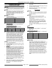
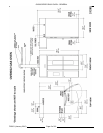
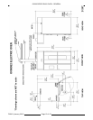
Export Ratings
â WATER:
1/2” NPT, 2.1 - 5.2 Bar cold water required, customer
to install in-line filter, shut off valve and line strainer.
Flow rate of 8 l/min.
Ð POWER:
Single supply connection provided: 200V/50-
60Hz/3ph/5.3A or 380-415V/50Hz/3ph
/ 2.8 - 2.5A
circuit required.
1 kVA transformer supplied for control circuit
operation voltage of 110V. This is a multifunction
transformer, so output voltage should be verified
before operation. Some wiring may be required to
obtain proper output voltage.
Oven fan (1.1kW) operates @ 380-415V 3ph 50 Hz
2.4- 2.2A
Voltage Full Load AMPS Heaters Rating
200/50 - 60/3 74 AMPS 24 kW
380 - 415/50/3 46 - 50 AMPS 29 - 34 kW
Ñ HOOD VENT:
20.3 cm DIA. Connection collar. Customer is to
supply duct and ventilator fan per federal and/or local
codes. Chamber vent (steam) and combustion
exhaust are discharged into the hood. Oven provides
a relay to activate a customer supplied and powered
contactor/relay, so that when oven is powered up
external fan will operate. The hood requires a
minimum of 19.5 m
3
/min for safe operation. For fan
calculation purposes you should assume 0.15 kPa
resistance through the hood. Grease filters (optional)
may be installed in the hood instead of standard
baffle.
F25361 (January 2010)Page 9 of 60