


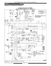

OV500 SERIES RACK OVEN - ELECTRICAL OPERATION
Ignition Control Module ..... Controls and monitors gas heating. Energizes gas valve coil, hot surface ignitor,
draft inducer, and monitors presence of flame.
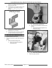
Hot Surface Ignitor ......... When energized, ignites gas.
Roll Out Switch............ Opens if flame goes beyond confined area of heat exchanger and into control
compartment. At 350EF. (177EC.) opens circuit to ignition module (manual
reset).
Flame Sensor ............. Monitors flame at the burner.
Water Solenoid - SV1 ....... When energized, allows water to flow onto oven steam generator.
Cir. Fan Motor - M1......... Circulates air around heat exchanger tubes and into oven cavity.
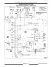
Cir. Fan Motor
Contactor - MR1 ........... Controls power to circulation fan motor.
Rotator Motor - M4 ......... When energized, turns baking rack.
Overload - OL1 ............ Monitors current to circulation motor.
Overload - OL2 ............ Monitors current to rotator and rack lift motors (optional).
Draft Inducer Motor - M3 .... When energized, drives fan to generate draft required for proper burner
operation, and exhausts combustion products into hood vent.
Temperature Sensor ....... Monitors air temperature in the oven cavity and sends signal to control board.
Vent Motor - M2............ When energized operates oven cavity vent.
Vent Position Switch ....... Allows controller to monitor the oven cavity vent (open or closed).
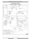
Rack Position Switch #1 .... Allows CR3 (Rack Position Relay) to be energized when door is open and rack
is in load/unload position.
Rack Position Switch #2 .... Signals rack position to control. Switch is operated when the rack is in position
for rack removal. (Centered in door opening).
Rack Lift Relay - CR4 ....... When energized, provides door input to controller, and a path for power to LS1
and LS2.
Rack Position Relay - CR3 . . . When energized, switches power from LS1 to LS2. Has a latching circuit.
Back Up Relay -CR2 ........ If open, closes vent on power up when back up controls are used.
Hood Vent Relay -CR1 ...... CR1 - Powers roof mounted vent motor and allows ignition module to be reset
after a lock-out.
Rack Lift Switch #1- LS1 .... Allows rack to stop in the rased position and rack to turn.
Rack Lift Switch #2- LS2 .... Allows rack to stop in the load/unload position.
Rack Lift Motor - M5 ........ M5 - Raises and lowers rack.
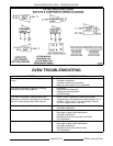
OVEN SEQUENCE OF
OPERATION
Oven Idle Mode
Idle mode exist when the supply voltage is at the
oven control and the control power switch has been
turned off for a minimum of 20 minutes.
1. Supply voltage to control with clock displayed
(A1 lit).
2. 120V present at the following components.
A. Control board / rack position switch #2 /
vent position switch / F1 of ignition module
/ CR4 contacts / 24V transformer door
switch circuit / 24V transformer heating
circuit.
3. If door is closed (A2 lit).
4. If door is open (A2 not lit) and rack in
load/unload position.
A. CR3 energized.
5. Vent closed (A3 lit).
6. Hood vent output (A5 lit).
A. CR1 energized and hood mounted fan de-
energized.
7. Interior lights will light if door is opened (A9 lit).
8. Neutral to one side of the following
components.
F25361 (January 2010)
Page 48 of 60