


A-4
INSTALLATION
SQUARE WAVE TIG 255
Return to Section TOC Return to Section TOC Return to Section TOC Return to Section TOC
Return to Master TOC Return to Master TOC Return to Master TOC Return to Master TOC
RECONNECT PROCEDURE
On multiple input voltage welders, be sure the recon-
nect panel is connected per the following instructions
for the voltage being supplied to the welder.
Failure to follow these instructions can cause immedi-
ate failure of components within the welder.
___________________________________________
Welders are shipped connected for the highest input
voltage as listed on the rating Plate. To change this
connection for a different input voltage, reconnect the
power strap (P) to the terminal corresponding to the
input voltage used. Designations on reconnect panel,
LOW, MID and HIGH correspond to the nameplate
input voltages of a triple voltage welder. Dual voltage
welders use only LOW and HIGH. Single voltage
welders use only HIGH.
EXAMPLE: On a 208/230/460 volt welder, LOW is
208V, MID is 230V, and HIGH is 460V.
Fuse the input circuit with the recommended super lag
fuses or delay type
1
circuit breakers. Choose an input
and grounding wire size according to local or national
codes, refer to Specification page at the beginning of
this chapter. Using fuses or circuit breakers
smaller than recommended may result in “nuisance”
shut-offs from welder inrush currents even if not
welding at high currents.
Unbalanced AC TIG welding draws higher input
currents than those for stick, DC TIG, or Balanced AC
TIG welding. The welder is designed for these higher
input currents. However, where unbalanced AC TIG
welding above 180 amps is planned, the higher input
currents require larger input wire sizes and fuses.
Refer to Specification page at the beginning of this
chapter.
The Square Wave TIG 255 should be permanently
wired into the power system. Plugs or connectors
are not recommended.
1
Also called “inverse time” or “thermal/magnetic” circuit breakers; circuit
breakers which have a delay in tripping action that decreases as the magni-
tude of the current increases.
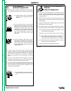
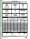
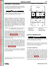
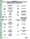
FIGURE A.2. - FRONT PANEL
1. CONTROL AND DISPLAY AREA 5. OPTIONAL WATER SOLENOID
2. POWER SWITCH 6. GAS SOLENOID
3. THERMOSTATIC 7. WORK (LEFT) AND
PROTECTION LIGHT ELECTRODE TERMINALS
4. POLARITY SWITCH 8. REMOTE RECEPTACLE
OUTPUT CONNECTIONS
To avoid receiving a high frequency shock, keep the
TIG torch and cables in good condition.
___________________________________________
See Figure A.2 for the location of the work and
electrode terminals, the gas and optional water
solenoids, and the Remote Receptacle.
TIG TORCH CONNECTION
TIG welding torches come with 12.5 ft (3.8m) and 25 ft
(7.6m) cables. Use the shorter length whenever
possible to minimize possible radio interference
problems. With power source off, connect the torch
cable to the “Electrode” terminal on the welder.
Connect a separate work cable to the “Work” terminal
of the welder. See Table A.1 for recommended work
cable sizes. Both work and electrode cables should be
routed through the cable strain relief holes provided in
the base directly below the welding output terminals.
DC
DC
AC
O
I
POWER
WARNING
ELECTRODE
WORK
GAS
IN
OUT
WATER
IN
OUT
DO NOT SWITCH
WHILE WELDING
L9119-1
L9119-2
REMOTE
1
2
3
4
5
6
7
8
WARNING
CAUTION