


SQUARE WAVE TIG 255
Return to Section TOC Return to Section TOC Return to Section TOC Return to Section TOC
Return to Master TOC Return to Master TOC Return to Master TOC Return to Master TOC
E-2
THEORY OF OPERATION
OUTPUT RECTIFICATION AND FEEDBACK CONTROL
LINE
SWITCH
R
E
C
O
N
N
E
C
T
MAIN
TRANSFORMER
X2
X1
POWER
FACTOR
CAPACITORS
FAN
115VAC
PROTECTION
SNUBBER
BOARD
ARC START
115 VAC
GATE SIGNALS
HI-FREQ
115 VAC
CONTROL
BOARD
LCD DISPLAY
KEYPAD
LED
BOARD
KEYPAD
HIGH VOLTAGE
TRANSFORMER
CIRCUIT
115 VAC
115 VAC
REMOTE
RECEPTACLE
115 VAC
RECEPTACLE
CONTROL
TRANSFORMER
24 VAC
18 VAC
16 VAC
HIGH FREQUENCY SPARK
WORK
ELECTRODE
HI-FREQ
TRANSFORMER
BY-PASS
BOARD
POLARITY
SWITCH
CHOKE
FEED BACK
GATE SIGNALS
AC
AC
DC+
DC-
SCR
BRIDGE
SHUNT
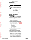
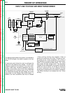
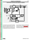
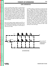
The AC output from the main transformer secondary
is rectified and controlled through the SCR bridge.
Output current is sensed at the shunt, as a low volt-
age signal, and fed back to the control board. The
control board compares the commands of the keypad
(or remote control) with the shunt feedback signal.
The appropriate gate firing pulses are generated by
the control board and applied to the SCR bridge
through the protection / snubber board. The control
board controls the firing of the SCRs, thus controlling
the output of the machine. See SCR Operation. The
control board also powers and commands the keypad
LED board and the display board.