


SQUARE WAVE TIG 255
Return to Section TOC Return to Section TOC Return to Section TOC Return to Section TOC
Return to Master TOC Return to Master TOC Return to Master TOC Return to Master TOC
F-29
TROUBLESHOOTING & REPAIR
ACTIVE SCR TEST
(continued)
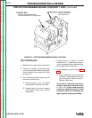
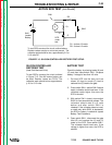
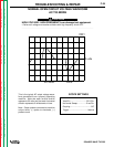
PROTECTION/SNUBBER
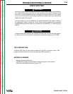
L9255
J10
J11
J12 J13
J14
J15
REMOVE PLUGS J10 & J13
TEST PROCEDURE
1. Remove main supply power to machine
2. Remove plugs J10 and J13 from protec-
tion/snubber board. See Figure F.13.
3. Remove red insulating paint from heat
sink test points. See Figure F.14. DO
NOT DISASSEMBLE THE HEAT
SINKS.
FIGURE F.13 - PROTECTION/SNUBBER BOARD PLUG LOCATIONS.
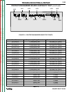
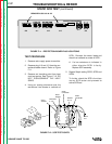
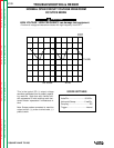
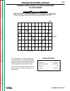
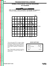
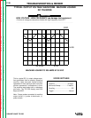
SCR1
ANODE
CATHODE
(1 & 2)
SCR2
ANODE
SCR3
CATHODE
SCR4
CATHODE
ANODE
(3 & 4)
PLUG
P10
FIGURE F.14 - SCR TEST POINTS.
4. Perform test procedure as outlined in
Figure F.15. Repeat test for all four
SCR’s
5. Replace any SCR assembly that does
not pass test in Step 4