


SQUARE WAVE TIG 255
Return to Section TOC Return to Section TOC Return to Section TOC Return to Section TOC
Return to Master TOC Return to Master TOC Return to Master TOC Return to Master TOC
F-24
TROUBLESHOOTING & REPAIR
ARC START TRIGGER CIRCUIT TEST
(continued)
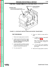
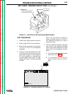
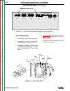
CONTROL BOX
CONTROL BOARD LOCATED INSIDE
PROTECTION/SNUBBER BOARD
LOCATED ON BACK OF CONTROL BOX
SUPORT CASE BACK
AND CENTER BAFFLE
WITH WOOD 2 X 4
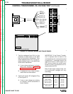
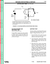
TEST PROCEDURE
1. Remove main supply power to machine
2. Remove plug J6 from the control board
3. Close the arc start switch or jumper pins
“D” and “E” at the six pin amphenol
receptacle.
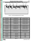
4. Check for continuity between pins 10J6
and 3J6 at plug J6 on the wiring har-
ness. Refer to Figure F.8. If 8.4 ohms to
6.0 ohms resistance is indicated then
arc start trigger circuit is okay. If a high
resistance or open is read then proceed
to Step 5.
Note: If arc start switch is opened or
jumper removed from pins “D” and “E”
the measured resistance in Step 4
should be infinite.
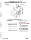
5 Test the resistance between 10J6 plug
and 10J12 on the projection/snubber
board. Also check resistance from 3J6
plug to 3J12 on the projection/ snubber
board.
A. If zero ohms resistance is indicated,
test is okay. Go to Step 6.
B. If a resistance of any value is
shown, check wires and connec-
tions.
FIGURE F.7 - LOCATION OF PROTECTION/SNUBBER BOARD.
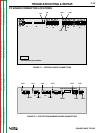
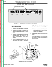
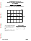
FIGURE F.8 - CONTROL BOARD TEST POINTS.
SQUARE WAVE 255 CONTROL
G2150
J1
J2
J3
J4
J5
J6
J7
J8
PLUG J6 REMOVED
3J6
10J6