


SQUARE WAVE TIG 255
Return to Section TOC Return to Section TOC Return to Section TOC Return to Section TOC
Return to Master TOC Return to Master TOC Return to Master TOC Return to Master TOC
E-5
THEORY OF OPERATION
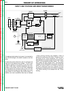
LINE
SWITCH
R
E
C
O
N
N
E
C
T
MAIN
TRANSFORMER
X2
X1
POWER
FACTOR
CAPACITORS
FAN
115VAC
PROTECTION
SNUBBER
BOARD
ARC START
115 VAC
GATE SIGNALS
HI-FREQ
115 VAC
CONTROL
BOARD
LCD DISPLAY
KEYPAD
LED
BOARD
KEYPAD
HIGH VOLTAGE
TRANSFORMER
CIRCUIT
115 VAC
115 VAC
REMOTE
RECEPTACLE
115 VAC
RECEPTACLE
CONTROL
TRANSFORMER
24 VAC
18 VAC
16 VAC
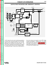
HIGH FREQUENCY SPARK
WORK
ELECTRODE
HI-FREQ
TRANSFORMER
BY-PASS
BOARD
POLARITY SWITCH
(AC POSITION)
CHOKE
FEED BACK
GATE SIGNALS
AC
AC
DC+
DC-
SCR
BRIDGE
SHUNT
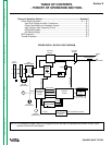
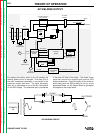
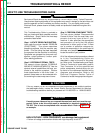
By rotating the polarity switch to the AC position the
welding power circuit is changed. One lead (X2) of
the main transformer secondary is connected to the
machine’s output work stud. The other secondary
lead (X1) is connected to one of the AC connections
on the SCR bridge. The electrode stud is connected
to the other AC side of the bridge. The choke is now
electrically across the negative and positive SCR
bridge connections. Due to the ability of the choke to
store energy and the SCR’s ability to turn on at the
appropriate times, an AC Square Wave is developed
and applied to the output studs.
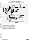
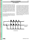
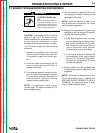
AC WELDING OUTPUT
CHOKE
WORK
ELECTRODE
PRIMARY
1Ø
G
G
G
G
DC
AC WELDING CIRCUIT
AC