


SQUARE WAVE TIG 255
Return to Section TOC Return to Section TOC Return to Section TOC Return to Section TOC
Return to Master TOC Return to Master TOC Return to Master TOC Return to Master TOC
F-21
TROUBLESHOOTING & REPAIR
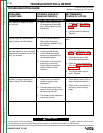
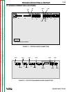
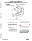
PROTECTION/SNUBBER BOARD CONTINUITY TEST
(continued)
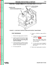
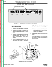
CONTROL BOX
PROTECTION/SNUBBER BOARD
LOCATED ON BACK OF CONTROL BOX
SUPORT CASE BACK
AND CENTER BAFFLE
WITH WOOD 2 X 4
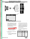
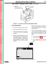
TEST PROCEDURE
1. Remove main supply power to machine.
2. Locate and remove all harness plugs
from the protection/snubber board locat-
ed on the back of the control box. Refer
to Figure F.5.
3. The protection/snubber board may be
removed to simplify test.
A. Remove three 8 - 32 x 1/4” Phillips
head screws from bottom of board
B. Release board from nylon supports
with needle nose pliers or small
screw driver
4. Inspect board for “leaky” or burned
components. If questionable compo-
nents are observed then replace projec-
tion/snubber board. (See note.)
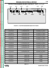
5. Check resistances per Continuity Table
F.6.
A. If any resistances do not meet the
Continuity Table specifications, pro-
jection/snubber board is faulty -
Replace. (See note.)
Note: When installing projection/
snubber board be sure that the three
8 - 32 x 1/4” Phillips head mounting
screws are tightened securely. These
conduction points are necessary for
high frequency by-pass grounding.
FIGURE F.5 - PROTECTION/SNUBBER BOARD LOCATION