


A-5
INSTALLATION
SQUARE WAVE TIG 255
Return to Section TOC Return to Section TOC Return to Section TOC Return to Section TOC
Return to Master TOC Return to Master TOC Return to Master TOC Return to Master TOC
DO NOT operate a water-cooled torch unless water is
flowing. Water doesn’t flow until solenoid is actuated.
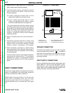
If using a water-cooled torch with a Magnum water
cooler, connect the cooler water outlet to the ‘Water
Valve In” fitting. Connect the TIG torch inlet to the
“Water Valve Out” fitting.
If using a water-cooled torch with a free-running water
supply, install a water line between the welder “Water
Inlet” and the supply. Include a strainer in the water
supply line to prevent dirt particles from obstructing
water flow in the valve and cooling chamber of the
TIG torch. Failure to do so could result in water valve
malfunction and overheating of the water-cooled
torch. Connect the torch water line to the welder
“Water Out” fitting. Use a nonmetallic drain line from
the electrode connection to the drain or water recircu-
lating pump.
For other water coolers or torches, consult the manu-
facturer’s instructions for the water cooler or TIG torch
being used.
Observe the safety precautions necessary for han-
dling and using compressed gas containers. Contact
your supplier for specific information.
___________________________________________
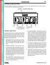
Connect the TIG torch gas and water fittings to the
welder fittings. Any torch with fittings that conform to
Compressed Gas Association (CGA) standards can be
used.
The welder fittings have the following threads: Gas
Inlet and Outlet: 5/8”-18 right-hand female; Water inlet
and Outlet: 5/8”-18 left-hand female. The cylinder of
inert shielding gas must be equipped with a pressure
regulator and flow meter. Install a hose between the
flow meter and gas inlet on the welder.
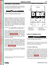
WARNING
Do not connect a TIG torch and stick electrode cable
at the same time. They will both be electrically HOT
whenever the output contactor is energized.
___________________________________________
WARNING
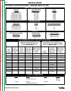
TABLE A.1
Cable Sizes for Combined Lengths of Copper
Electrode and Work Cable
Machine Size
Lengths up to
100 ft 100 to 200 ft 200 to 250 ft
255 Amp
40% Duty Cycle #2 (35mm
2
) #1 (45mm
2
) 1/0 (55mm
2
)
STICK ELECTRODE CABLE CONNECTION
Turn the Power switch Off. Run the electrode and
work cables through the strain relief holes below the
welding output terminals, and connect the cables to
the proper terminals. This strain relief prevents dam-
age to the welding output terminals if the cables are
pulled excessively. Select cable size according to
Table A.1.