


SQUARE WAVE TIG 255
Return to Section TOC Return to Section TOC Return to Section TOC Return to Section TOC
Return to Master TOC Return to Master TOC Return to Master TOC Return to Master TOC
F-19
TROUBLESHOOTING & REPAIR
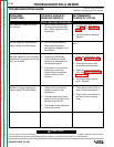
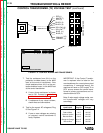
CONTROL TRANSFORMER (T2) VOLTAGE TEST
(continued)
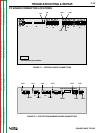
SQUARE WAVE 255 CONTROL
G2150
BLACK
BLACK
RED
WHITE
RED (1)
YELLOW (10)
BLUE
ORANGE
ORANGE
BLUE
YELLOW
(7)
(2)
(3)
(9)
(4)
(11)
(5)
(12)
(6)
1
2
3
4
5
6
7
8
9
10
11
12
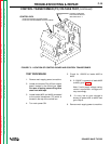
VIEWED FROM END
PLUG P8
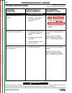
7. Test the resistance from 8J14, on the
protection/ snubber board, to the #432
lead at the control transformer. Also
check resistance from 4J14, on the pro-
tection/snubber board, to the #433 lead
at the control transformer.
A. If zero ohms resistance is shown
test is OK. Proceed to protection/
snubber board continuity test.
B. If resistance of any value is shown,
check wires and connections.
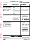
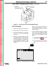
8. Test for the correct AC voltages at Plug
8. See Figure F-4.
A. If one or more voltages are missing
or incorrect, control transformer is
faulty. Replace.
Secondary Approximate
Lead Colors Plug P8 Voltages
Red to Red 1 to 2 36 VAC
Red to White 1 to 7 18 VAC
Yellow to Yellow 4 to 10 16 VAC
Black to Black 3 to 9 24 VAC
Orange to Orange 6 to 12 16 VAC
Blue to Blue 5 to 11 16 VAC
FIGURE F.4 - CONTROL BOARD AND TRANSFORMER.
IMPORTANT: If the Control Transfor-
mer is replaced refer to label on the
new transformer for correct primary lead
connections. If connected wrong, the
machine will have no OCV output. If no
OCV occurs reverse the control trans-
former’s primary connections and re-
check machine’s OCV.
Note: If main supply voltage varies, con-
trol transformer voltages will vary
accordingly.