


SQUARE WAVE TIG 255
Return to Section TOC Return to Section TOC Return to Section TOC Return to Section TOC
Return to Master TOC Return to Master TOC Return to Master TOC Return to Master TOC
F-30
TROUBLESHOOTING & REPAIR
ACTIVE SCR TEST
(continued)
SW1
R2
SW2
R1
A
G
C
V
SCR
under
test
R1= 4 ohms /10 watts
R2= 3 ohms/ 10 watts
6volt
Lantern
Battery
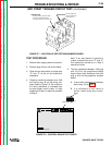
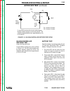
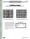
To test SCRs construct the circuit outlined above.
Resistor values are plus or minus ten percent. The
voltmeter scale should be low, approximately 0-5 or
0-10 volts DC.
SILICON CONTROLLED
RECTIFIER TEST
(Heat Sink Mounted Units)
To test SCR’s construct the circuit outlined
in Figure F.15. One 6V lantern battery can
be used. Resistor values are Ò10%. The
voltmeter scale should be low, approximate-
ly 0-5 or 0-10 volts.
BATTERY TEST
Check the battery by shorting leads (A) and
(C) and then close switch SW-1. Re-place
battery if voltage is less than 4.5 volts.
1. Connect SCR into the test circuit as
shown (A) lead to anode (C) lead to
cathode and (G) lead to the gate.
2. Close switch SW-1 (switch SW-2 should
open), voltmeter should read zero. If the
voltmeter reads higher than zero the
SCR is shorted.
3. With switch SW-1 closed, close switch
SW-2 for two seconds and release. The
voltmeter should read 3 to 6 volts
before and after switch SW-2 is
released. If the voltmeter does not read,
or reads only while SW-2 is depressed,
the SCR or battery is defective (repeat
Battery Test Procedure).
4. Open switch SW-1, disconnect the gate
lead (G) and reverse the (A) and (C)
leads on the SCR. Close switch SW-1.
The voltmeter should read zero. If the
voltage is higher than zero, the SCR is
shorted.
FIGURE F.15 - SILICON CONTROLLED RECTIFIER TEST SETUP.
12/95