


35
12. Additional information
Brief fault finding notes and a list of replacement parts are given in this section.
Note that this equipment should only be dismantled by properly trained personnel. Removing the
outer cover exposes potentially lethal power voltages.
There are no user serviceable parts within this equipment.
Fault Finding
Should you encounter problems with your TCY contact Omega Flow Engineering for assistance.
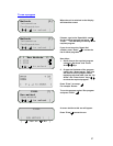
Fuses
If neither the power light nor display on the front panel is lit, one of the two fuses may have blown.
Check that there is no external cause, such as a faulty plug or lead. Check both fuses and replace
the faulty fuse with a new one of the correct value (fuse values are given on the label next to the
power inlet). Note that fuses should only be replaced by a qualified electrician.
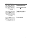
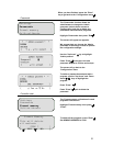
The holder for the two fuses is built into the power input socket. First remove the power cable and
then gently prise the fuse drawer open with a flat-bladed screwdriver or similar tool.
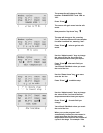
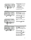
Each fuse can be removed by using the screwdriver as a lever.
Exchange the faulty fuse in the fuse holder for a working fuse of the correct value. Finally, replace
the fuse drawer in the fuse compartment and push the drawer shut.
Fuses which blow repeatedly indicate a serious fault and you should return the unit to your
supplier for repair.
The heated lid over-temperature cut-out
The heated lid is fitted with an independent circuit to protect it from overheating. In the unlikely
event of an over-temperature problem with the lid, the unit is fitted with a thermal fuse which will
remove power to the heater plate should the maximum temperature be exceeded.
Insulation testing
This equipment is fitted with RFI suppression circuitry. Any check of the electrical insulation by
means of high voltage dielectric testing (for example as in BS EN 61010-1) must be carried out
using only a TCY voltage.
This unit contains semiconductor components which may be damaged by electric field effects.
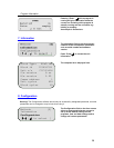
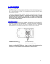
Interchangeable blocks
The block can be removed and replaced by another of the same sort or of a different sort. The
software will register the change and set up the unit for the new block.
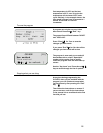
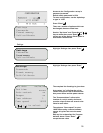
Remove the four screws on the underside of the unit and drop the block/fan assembly down.
Unplug the assembly from the wiring and remove the assembly from the unit. Refitting the
block/fan assembly is the reverse procedure; be careful of the wires as you refit the block.